User Manual
Page 1
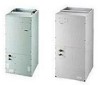
... YOUR LOCAL AUTHORITIES. Installation & Operation Manual Air Handler 13 SEER 2 3 4 5 Ton WARNING WHEN THIS APPLIANCE IS INSTALLED IN AN ENCLOSED AREA, SUCH AS A GARAGE OR UTILITY ROOM, WITH ANY CARBON MONOXIDE PRODUCING DEVICES (i.e. AUTOMOBILE, SPACE HEATER, WATER HEATER,ETC.) INSURE THAT THE ENCLOSED AREA IS PROPERLY VENTILATED. ONLY FACTORY AUTHORIZED KITS OR ACCESSORIES SHOULD BE USED WHEN INSTALLING OR MODIFYING THIS APPLIANCE...
... YOUR LOCAL AUTHORITIES. Installation & Operation Manual Air Handler 13 SEER 2 3 4 5 Ton WARNING WHEN THIS APPLIANCE IS INSTALLED IN AN ENCLOSED AREA, SUCH AS A GARAGE OR UTILITY ROOM, WITH ANY CARBON MONOXIDE PRODUCING DEVICES (i.e. AUTOMOBILE, SPACE HEATER, WATER HEATER,ETC.) INSURE THAT THE ENCLOSED AREA IS PROPERLY VENTILATED. ONLY FACTORY AUTHORIZED KITS OR ACCESSORIES SHOULD BE USED WHEN INSTALLING OR MODIFYING THIS APPLIANCE...
User Manual
Page 2
... General Physical dimensions Replacement Parts Source Installation Requirements Air Flow Orientation Horizontal Left-Hand Instructions Refrigerant Tubing Condensate Removal Electrical Connections Thermostat Wiring Orifice Change Circulating Air Duct Blower Performance Start-up Regular Maintenance Model Number Explanation PAGE 2 3 6 6 7 8 9 10 10 11 12 14 14 15 15 16 The United States Environmental Protection Agency (EPA) has issued various regulations regarding the introduction and disposal of refrigerants introduced into this unit.Failure to...
... General Physical dimensions Replacement Parts Source Installation Requirements Air Flow Orientation Horizontal Left-Hand Instructions Refrigerant Tubing Condensate Removal Electrical Connections Thermostat Wiring Orifice Change Circulating Air Duct Blower Performance Start-up Regular Maintenance Model Number Explanation PAGE 2 3 6 6 7 8 9 10 10 11 12 14 14 15 15 16 The United States Environmental Protection Agency (EPA) has issued various regulations regarding the introduction and disposal of refrigerants introduced into this unit.Failure to...

User Manual
Page 4
PHYSICAL DIMENSIONS of 3 Ton PLASTIC BREAKER COVER INLET BOTTOM SIDE VIEW ELECTRICAL POWER SUPPLY SUCTION LINE LIQUID LINE LOW VOLT SUPPLY ELECTRICAL POWER SUPPLY 4
PHYSICAL DIMENSIONS of 3 Ton PLASTIC BREAKER COVER INLET BOTTOM SIDE VIEW ELECTRICAL POWER SUPPLY SUCTION LINE LIQUID LINE LOW VOLT SUPPLY ELECTRICAL POWER SUPPLY 4

User Manual
Page 5
PHYSICAL DIMENSIONS of 4,5 Ton PLASTIC BREAKER COVER INLET BOTTOM SIDE VIEW ELECTRICAL POWER SUPPLY SUCTION LINE LIQUID LINE LOW VOLT SUPPLY ELECTRICAL POWER SUPPLY 5
PHYSICAL DIMENSIONS of 4,5 Ton PLASTIC BREAKER COVER INLET BOTTOM SIDE VIEW ELECTRICAL POWER SUPPLY SUCTION LINE LIQUID LINE LOW VOLT SUPPLY ELECTRICAL POWER SUPPLY 5
User Manual
Page 6
... must be installed on the rating plate. Heating and cooling equipment located in garages, which may generate a glow, spark or flame capable of vehicles. The horizontal left and downflow positions require product modification. This product is a leak or main drain blockage. In an attic installation a secondary drain pan must be subjected to the owner. Appliances installed in a building, permanently identify the unit as to...
... must be installed on the rating plate. Heating and cooling equipment located in garages, which may generate a glow, spark or flame capable of vehicles. The horizontal left and downflow positions require product modification. This product is a leak or main drain blockage. In an attic installation a secondary drain pan must be subjected to the owner. Appliances installed in a building, permanently identify the unit as to...
User Manual
Page 7
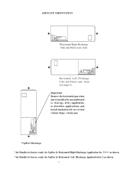
front (see page 6) Important: Remove the horizontal pan when unit is installed in unconditioned i.e. (Garage, Attic ) application, or downflow applications, and install insulation kit on vertical ( donut shape ) drain pan. *Upflow Discharge *Air Handler is factory ready for Upflow & Horizontal Right Discharge Application for 3*4*5 as shown. *Air Handler is factory ready for Upflow & Horizontal Left Discharge Application for 2 as shown. 7 AIR FLOW ORIENTATION *Horizontal Right Discharge Tube and Drain conn. front Horizontal Left Discharge Tube and Drain conn.
front (see page 6) Important: Remove the horizontal pan when unit is installed in unconditioned i.e. (Garage, Attic ) application, or downflow applications, and install insulation kit on vertical ( donut shape ) drain pan. *Upflow Discharge *Air Handler is factory ready for Upflow & Horizontal Right Discharge Application for 3*4*5 as shown. *Air Handler is factory ready for Upflow & Horizontal Left Discharge Application for 2 as shown. 7 AIR FLOW ORIENTATION *Horizontal Right Discharge Tube and Drain conn. front Horizontal Left Discharge Tube and Drain conn.

User Manual
Page 8
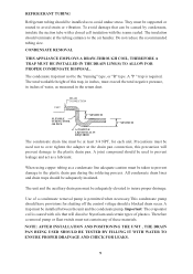
... access panels and flowrator making sure not to the user. 9) WARNING: The "A" coil contains 150 p.s.i.g. Plastic Drain cover Fig.1 oval gasket WARNING: If incorrect knockouts are removed, flooding will cancel product warranty. of the cavity. 6) Replace the J-shape metal bracket or brackets on the vertical drain pan and place the plastic oval gasket on the secondary drain if used. 8) In all cooling applications, a secondary drain pan...
... access panels and flowrator making sure not to the user. 9) WARNING: The "A" coil contains 150 p.s.i.g. Plastic Drain cover Fig.1 oval gasket WARNING: If incorrect knockouts are removed, flooding will cancel product warranty. of the cavity. 6) Replace the J-shape metal bracket or brackets on the vertical drain pan and place the plastic oval gasket on the secondary drain if used. 8) In all cooling applications, a secondary drain pan...
User Manual
Page 9
... process. UNIT DRAIN CONNECTION FLEXIBLE TUBING-HOSE OR PIPE 2" MINIMUM 3" MINIMUM A POSITIVE LIQUID SEAL IS REQUIRED The condensate drain line must be at the drain pan connection, this trap, in the return duct. Precautions must be used to avoid strain or vibration. The unit and the auxiliary drain pan must be the "running" type, or "R" type. A trap must not be supported or routed...
... process. UNIT DRAIN CONNECTION FLEXIBLE TUBING-HOSE OR PIPE 2" MINIMUM 3" MINIMUM A POSITIVE LIQUID SEAL IS REQUIRED The condensate drain line must be at the drain pan connection, this trap, in the return duct. Precautions must be used to avoid strain or vibration. The unit and the auxiliary drain pan must be the "running" type, or "R" type. A trap must not be supported or routed...
User Manual
Page 10
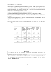
... of the unit. The wiring diagram included in that kit. ELECTRICAL CONNECTIONS The required electrical power supply information is located on the series and rating plate on the air handler. Wiring selection must be applied to the electrical requirements for that kit. When an optional heat kit is installed refer to the electrical requirements in the heat kit must be installed within sight of copper connections are recommended inside the control box...
... of the unit. The wiring diagram included in that kit. ELECTRICAL CONNECTIONS The required electrical power supply information is located on the series and rating plate on the air handler. Wiring selection must be applied to the electrical requirements for that kit. When an optional heat kit is installed refer to the electrical requirements in the heat kit must be installed within sight of copper connections are recommended inside the control box...
User Manual
Page 11
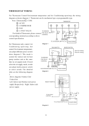
... Thermostat only control Air Diagram 1 Conditioning open /stop , hot control Environment temperature, can adopt multi-connect switch or select switch. The detailed infor see the following diagram TO INDOOR FAN RELAY CONTROL RD RD BL BL 24V O YCR COM TO OUTDOOR UNIT R,C,Y,O TRANSFORMER Diagram 2 3. Above diagram: Outdoor Unit Connection Left: Indoor and Outdoor unit power supply Respectively Right: Indoor unit power supply. 1 2 SELECT SWITCH 3 4 5 6 OFF FAN ONLY E. This mode is RUN SWITCH MODE SWITCH Open for heating Close for cooling control the indoor unit & heat pump...
... Thermostat only control Air Diagram 1 Conditioning open /stop , hot control Environment temperature, can adopt multi-connect switch or select switch. The detailed infor see the following diagram TO INDOOR FAN RELAY CONTROL RD RD BL BL 24V O YCR COM TO OUTDOOR UNIT R,C,Y,O TRANSFORMER Diagram 2 3. Above diagram: Outdoor Unit Connection Left: Indoor and Outdoor unit power supply Respectively Right: Indoor unit power supply. 1 2 SELECT SWITCH 3 4 5 6 OFF FAN ONLY E. This mode is RUN SWITCH MODE SWITCH Open for heating Close for cooling control the indoor unit & heat pump...

User Manual
Page 12
...: Indoor unit power supply. 1 2 SELECT SWITCH 3 4 5 6 TO FAN RELAY CONTROL RD BL RD BL CY 24V COM TO OUTDOOR UNIT C,Y TRANSFORMER Diagram 6 12 This mode is control the indoor unit & cooling only outdoor unit at the same time no air supply mode. R : AC24V TERMOSTAT Y : COMPRESSOR G Y R C G : FAN For detailed Thermostat, please connect corresponding terminal according to above control specification. The detailed infor see the following diagram 6. For Thermostat Control Environment-temperature and Air Conditioning open /stop , the wiring diagram as shown diagram...
...: Indoor unit power supply. 1 2 SELECT SWITCH 3 4 5 6 TO FAN RELAY CONTROL RD BL RD BL CY 24V COM TO OUTDOOR UNIT C,Y TRANSFORMER Diagram 6 12 This mode is control the indoor unit & cooling only outdoor unit at the same time no air supply mode. R : AC24V TERMOSTAT Y : COMPRESSOR G Y R C G : FAN For detailed Thermostat, please connect corresponding terminal according to above control specification. The detailed infor see the following diagram 6. For Thermostat Control Environment-temperature and Air Conditioning open /stop , the wiring diagram as shown diagram...
User Manual
Page 13
... recommended to minimize the possibility of noise transmission. THE CAPACITY OF THE OUTDOOR UNIT SHOULD NEVER EXCEED THE CAPACITY OF THE INDOOR UNIT. See piston kit table 1 in this unit match the comparable capacity of the outdoor unit. The use of flexible duct connectors is greater in capacity than the outdoor condenser, the orifice must be replaced before any tubing connections are made...
... recommended to minimize the possibility of noise transmission. THE CAPACITY OF THE OUTDOOR UNIT SHOULD NEVER EXCEED THE CAPACITY OF THE INDOOR UNIT. See piston kit table 1 in this unit match the comparable capacity of the outdoor unit. The use of flexible duct connectors is greater in capacity than the outdoor condenser, the orifice must be replaced before any tubing connections are made...

User Manual
Page 14
... water column dry coil w/ filter) 4% reduction for differences encountered in the heat mode. 3) Measure the return air temperature. 4) Measure the supply temperature. The CFM can be checked by the following method; (The optional Heat Kit must be installed to obtain an average. 5) Subtract the return temperature from the supply temperature. This measurement should be done in various locations to continue with this procedure.) 1) All access panels...
... water column dry coil w/ filter) 4% reduction for differences encountered in the heat mode. 3) Measure the return air temperature. 4) Measure the supply temperature. The CFM can be checked by the following method; (The optional Heat Kit must be installed to obtain an average. 5) Subtract the return temperature from the supply temperature. This measurement should be done in various locations to continue with this procedure.) 1) All access panels...

User Manual
Page 15
... to initial start-up insure that the circulating air filter(s) is cleaned or replaced. Unit should be present. REGULAR MAINTENANCE WARNING DISCONNECT ALL POWER SUPPLIES BEFORE PERFORMING ANY SERVICE. A certified service technician should be obtained from vehicular or other services. 15 Low voltage wiring is not to allow for drainage. The only item to be objectionable odors, flammable vapors or products of combustion such...
... to initial start-up insure that the circulating air filter(s) is cleaned or replaced. Unit should be present. REGULAR MAINTENANCE WARNING DISCONNECT ALL POWER SUPPLIES BEFORE PERFORMING ANY SERVICE. A certified service technician should be obtained from vehicular or other services. 15 Low voltage wiring is not to allow for drainage. The only item to be objectionable odors, flammable vapors or products of combustion such...


