
Manual
Page 1
... to enable the Intel Smart Response Technology • The Intel Smart Response Technology requires a computer system with an Intel Z68 Chipset-based motherboard and an Intel Core series CPU. • The operating system must be installed to enter BIOS Setup during the POST (Power-On ... system before enabling the Smart Response Technology. 1. Enabling RAID mode in BIOS Setup 3. Enabling RAID mode in BIOS Setup: Turn on the motherboard you will be used for your data. 2. CMOS Setup Utility-Copyright (C) 1984-2011 Award Software Integrated Peripherals eXtreme Hard Drive (XHD) PCH...
... to enable the Intel Smart Response Technology • The Intel Smart Response Technology requires a computer system with an Intel Z68 Chipset-based motherboard and an Intel Core series CPU. • The operating system must be installed to enter BIOS Setup during the POST (Power-On ... system before enabling the Smart Response Technology. 1. Enabling RAID mode in BIOS Setup 3. Enabling RAID mode in BIOS Setup: Turn on the motherboard you will be used for your data. 2. CMOS Setup Utility-Copyright (C) 1984-2011 Award Software Integrated Peripherals eXtreme Hard Drive (XHD) PCH...

Manual
Page 2
Installing the operating system and drivers to the SATA disk: After setting the BIOS, you can begin to install all motherboard drivers, including the Intel Rapid Storage Technology driver. Launching the Intel Rapid Storage Technology utility to open the Intel Rapid Storage Technology ...utility. - 2 - Make sure the Intel Rapid Storage Technology driver version is complete, use the "Xpress Install" function of the motherboard driver disk to install the operating system. After the installation is 10.5 or above and restarting your system, find the IRST icon ...
Installing the operating system and drivers to the SATA disk: After setting the BIOS, you can begin to install all motherboard drivers, including the Intel Rapid Storage Technology driver. Launching the Intel Rapid Storage Technology utility to open the Intel Rapid Storage Technology ...utility. - 2 - Make sure the Intel Rapid Storage Technology driver version is complete, use the "Xpress Install" function of the motherboard driver disk to install the operating system. After the installation is 10.5 or above and restarting your system, find the IRST icon ...
Manual
Page 2
Motherboard GA-Z68A-D3H-B3 Apr. 29, 2011 Motherboard GA-Z68A-D3H-B3 Apr. 29, 2011
Motherboard GA-Z68A-D3H-B3 Apr. 29, 2011 Motherboard GA-Z68A-D3H-B3 Apr. 29, 2011
Manual
Page 3
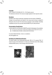
For product-related information, check on our website at: http://www.gigabyte.com Identifying Your Motherboard Revision The revision number on your motherboard revision before updating motherboard BIOS, drivers, or when looking for technical information. The trademarks mentioned in any ...information, carefully read the User's Manual. For example, "REV: 1.0" means the revision of the motherboard is the property of this manual may be made by GIGABYTE without GIGABYTE's prior written permission. All rights reserved. Example: Copyright © 2011 GIGA-BYTE TECHNOLOGY CO., LTD...
For product-related information, check on our website at: http://www.gigabyte.com Identifying Your Motherboard Revision The revision number on your motherboard revision before updating motherboard BIOS, drivers, or when looking for technical information. The trademarks mentioned in any ...information, carefully read the User's Manual. For example, "REV: 1.0" means the revision of the motherboard is the property of this manual may be made by GIGABYTE without GIGABYTE's prior written permission. All rights reserved. Example: Copyright © 2011 GIGA-BYTE TECHNOLOGY CO., LTD...
Manual
Page 4
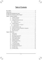
Table of Contents Box Contents...6 Optional Items...6 GA-Z68A-D3H-B3 Motherboard Layout 7 GA-Z68A-D3H-B3 Motherboard Block Diagram 8 Chapter 1 Hardware Installation 9 1-1 Installation Precautions 9 1-2 Product Specifications 10 1-3 Installing the CPU and CPU Cooler 13 1-3-1 Installing the CPU 13 1-3-2 Installing the CPU Cooler ...
Table of Contents Box Contents...6 Optional Items...6 GA-Z68A-D3H-B3 Motherboard Layout 7 GA-Z68A-D3H-B3 Motherboard Block Diagram 8 Chapter 1 Hardware Installation 9 1-1 Installation Precautions 9 1-2 Product Specifications 10 1-3 Installing the CPU and CPU Cooler 13 1-3-1 Installing the CPU 13 1-3-2 Installing the CPU Cooler ...
Manual
Page 6
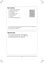
Optional Items 2-port USB 2.0 bracket (Part No. 12CR1-1UB030-5*R) 2-port SATA power cable (Part No. 12CF1-2SERPW-0*R) COM port cable (Part No. 12CF1-1CM001-3*R) - 6 - The box contents are for reference only. Box Contents GA-Z68A-D3H-B3 motherboard Motherboard driver disk User's Manual Quick Installation Guide Four SATA cables I/O Shield One 2-Way SLI bridge connector • The box contents above are subject to change without notice. • The motherboard image is for reference only and the actual items shall depend on the product package you obtain.
Optional Items 2-port USB 2.0 bracket (Part No. 12CR1-1UB030-5*R) 2-port SATA power cable (Part No. 12CF1-2SERPW-0*R) COM port cable (Part No. 12CF1-1CM001-3*R) - 6 - The box contents are for reference only. Box Contents GA-Z68A-D3H-B3 motherboard Motherboard driver disk User's Manual Quick Installation Guide Four SATA cables I/O Shield One 2-Way SLI bridge connector • The box contents above are subject to change without notice. • The motherboard image is for reference only and the actual items shall depend on the product package you obtain.
Manual
Page 7
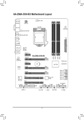
GA-Z68A-D3H-B3 Motherboard Layout KB_USB ATX_12V VGA_DVI LEVEL SHIFTER HDMI LEVEL SHIFTER OPTICAL CPU_FAN LGA1155 PWR_FAN ATX R_USB30 USB_LAN AUDIO Etron EJ168 PCIEX1_1 Realtek RTL8111E PCIEX16 PCIEX1_2 CODEC PCIEX4 PCIEX8 PCI1 iTE IT8728 PCI2 F_AUDIO COMA SPDIF_O GA-Z68A-D3H-B3 BAT DDR3_4 DDR3_2 DDR3_3 DDR3_1 Intel® Z68 B_BIOS M_BIOS PCIe to PCI Bridge SATA3_0 SATA3_1 SATA2_2 SATA2_3 SATA2_4 SATA2_5 CLR_CMOS F_USB4 F_USB2 F_USB1 TPM SYS_FAN1 F_USB3 SYS_FAN2 F_PANEL - 7 -
GA-Z68A-D3H-B3 Motherboard Layout KB_USB ATX_12V VGA_DVI LEVEL SHIFTER HDMI LEVEL SHIFTER OPTICAL CPU_FAN LGA1155 PWR_FAN ATX R_USB30 USB_LAN AUDIO Etron EJ168 PCIEX1_1 Realtek RTL8111E PCIEX16 PCIEX1_2 CODEC PCIEX4 PCIEX8 PCI1 iTE IT8728 PCI2 F_AUDIO COMA SPDIF_O GA-Z68A-D3H-B3 BAT DDR3_4 DDR3_2 DDR3_3 DDR3_1 Intel® Z68 B_BIOS M_BIOS PCIe to PCI Bridge SATA3_0 SATA3_1 SATA2_2 SATA2_3 SATA2_4 SATA2_5 CLR_CMOS F_USB4 F_USB2 F_USB1 TPM SYS_FAN1 F_USB3 SYS_FAN2 F_PANEL - 7 -
Manual
Page 8
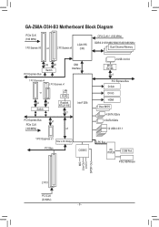
GA-Z68A-D3H-B3 Motherboard Block Diagram PCIe CLK (100 MHz) 1 PCI Express x16 or 2 PCI Express x8 LGA1155 CPU CPU CLK+/- (100 MHz) DDR3 2133/1866/1600/1333/1066 ...
GA-Z68A-D3H-B3 Motherboard Block Diagram PCIe CLK (100 MHz) 1 PCI Express x16 or 2 PCI Express x8 LGA1155 CPU CPU CLK+/- (100 MHz) DDR3 2133/1866/1600/1333/1066 ...
Manual
Page 9
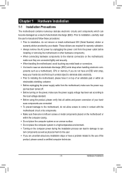
... hardware components to the internal connectors on the computer power during the installation process can lead to damage to system components as well as a motherboard, CPU or memory. Prior to installation, carefully read the user's manual and follow these procedures: •• Prior to installation, do...to the user. •• If you do not allow screws to come in a high-temperature environment. •• Turning on the motherboard, make sure the power supply voltage has been set according to the local voltage standard. •• Before using the product, please verify ...
... hardware components to the internal connectors on the computer power during the installation process can lead to damage to system components as well as a motherboard, CPU or memory. Prior to installation, carefully read the user's manual and follow these procedures: •• Prior to installation, do...to the user. •• If you do not allow screws to come in a high-temperature environment. •• Turning on the motherboard, make sure the power supply voltage has been set according to the local voltage standard. •• Before using the product, please verify ...
Manual
Page 12
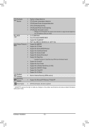
...ŠŠ Support for Xpress Install ŠŠ Support for Xpress Recovery2 ŠŠ Support for EasyTune * Available functions in EasyTune may differ by motherboard model. ŠŠ Support for Smart 6™ ŠŠ Support for Auto Green ŠŠ Support for eXtreme Hard Drive (X.H.D) ŠŠ... System ŠŠ Support for Microsoft® Windows 7/Vista/XP Form Factor ŠŠ ATX Form Factor; 30.5cm x 22.5cm * GIGABYTE reserves the right to make any changes to the product specifications and product-related information without prior notice.
...ŠŠ Support for Xpress Install ŠŠ Support for Xpress Recovery2 ŠŠ Support for EasyTune * Available functions in EasyTune may differ by motherboard model. ŠŠ Support for Smart 6™ ŠŠ Support for Auto Green ŠŠ Support for eXtreme Hard Drive (X.H.D) ŠŠ... System ŠŠ Support for Microsoft® Windows 7/Vista/XP Form Factor ŠŠ ATX Form Factor; 30.5cm x 22.5cm * GIGABYTE reserves the right to make any changes to the product specifications and product-related information without prior notice.
Manual
Page 13
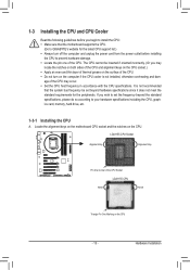
...the system bus frequency be inserted if oriented incorrectly. (Or you wish to set beyond the standard specifications, please do so according to GIGABYTE's website for the peripherals. age of the CPU Socket LGA1155 CPU Notch Notch Triangle Pin One Marking on the computer if the CPU ...cooler is not recommended that the motherboard supports the CPU. (Go to your hardware specifications including the CPU, graphics card, memory, hard drive, etc. 1-3-1 Installing the CPU A. LGA1155 ...
...the system bus frequency be inserted if oriented incorrectly. (Or you wish to set beyond the standard specifications, please do so according to GIGABYTE's website for the peripherals. age of the CPU Socket LGA1155 CPU Notch Notch Triangle Pin One Marking on the computer if the CPU ...cooler is not recommended that the motherboard supports the CPU. (Go to your hardware specifications including the CPU, graphics card, memory, hard drive, etc. 1-3-1 Installing the CPU A. LGA1155 ...
Manual
Page 14
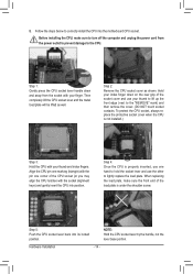
....) Step 3: Hold the CPU with the socket alignment keys) and gently insert the CPU into position. Step 5: Push the CPU socket lever back into the motherboard CPU socket. Step 2: Remove the CPU socket cover as well. Hardware Installation - 14 - Align the CPU pin one marking (triangle) with the pin one hand...
....) Step 3: Hold the CPU with the socket alignment keys) and gently insert the CPU into position. Step 5: Push the CPU socket lever back into the motherboard CPU socket. Step 2: Remove the CPU socket cover as well. Hardware Installation - 14 - Align the CPU pin one marking (triangle) with the pin one hand...
Manual
Page 15
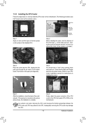
...removing the CPU cooler may adhere to the CPU. 1-3-2 Installing the CPU Cooler Follow the steps below to correctly install the CPU cooler on the motherboard. (The following procedure uses Intel® boxed cooler as the picture above shows, the installation is complete. Check that the Male and Female ... is to the CPU fan header (CPU_FAN) on installing the cooler.) Step 5: After the installation, check the back of thermal grease on the motherboard. Push down each push pin. Use extreme care when removing the CPU cooler because the thermal grease/tape between the CPU cooler and CPU may...
...removing the CPU cooler may adhere to the CPU. 1-3-2 Installing the CPU Cooler Follow the steps below to correctly install the CPU cooler on the motherboard. (The following procedure uses Intel® boxed cooler as the picture above shows, the installation is complete. Check that the Male and Female ... is to the CPU fan header (CPU_FAN) on installing the cooler.) Step 5: After the installation, check the back of thermal grease on the motherboard. Push down each push pin. Use extreme care when removing the CPU cooler because the thermal grease/tape between the CPU cooler and CPU may...
Manual
Page 16
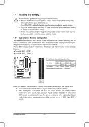
... mode with two memory modules, we recommend that memory of the same capacity, brand, speed, and chips be used . (Go to GIGABYTE's website for optimum performance. If you install them in only one DDR3 memory module is installed, the BIOS will double the original memory ... CPU limitations, read the following guidelines before you begin to insert the memory, switch the direction. 1-4-1 Dual Channel Memory Configuration This motherboard provides four DDR3 memory sockets and supports Dual Channel Technology. The four DDR3 memory sockets are unable to install the memory: ••...
... mode with two memory modules, we recommend that memory of the same capacity, brand, speed, and chips be used . (Go to GIGABYTE's website for optimum performance. If you install them in only one DDR3 memory module is installed, the BIOS will double the original memory ... CPU limitations, read the following guidelines before you begin to insert the memory, switch the direction. 1-4-1 Dual Channel Memory Configuration This motherboard provides four DDR3 memory sockets and supports Dual Channel Technology. The four DDR3 memory sockets are unable to install the memory: ••...
Manual
Page 17
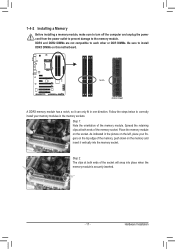
... power cord from the power outlet to prevent damage to correctly install your fingers on the top edge of the memory, push down on this motherboard. DDR3 and DDR2 DIMMs are not compatible to each other or DDR DIMMs. Be sure to install DDR3 DIMMs on the memory and insert it...
... power cord from the power outlet to prevent damage to correctly install your fingers on the top edge of the memory, push down on this motherboard. DDR3 and DDR2 DIMMs are not compatible to each other or DDR DIMMs. Be sure to install DDR3 DIMMs on the memory and insert it...
Manual
Page 18
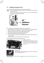
... slot. 333 Make sure the metal contacts on the top edge of the PCI Express slot to install an expansion card: • Make sure the motherboard supports the expansion card. Example: Installing and Removing a PCI Express Graphics Card: • Installing a Graphics Card: Gently push down on your operating system. Carefully read...
... slot. 333 Make sure the metal contacts on the top edge of the PCI Express slot to install an expansion card: • Make sure the motherboard supports the expansion card. Example: Installing and Removing a PCI Express Graphics Card: • Installing a Graphics Card: Gently push down on your operating system. Carefully read...
Manual
Page 19
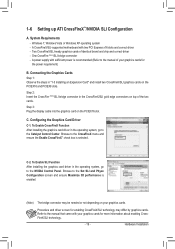
.... To Enable CrossFireX Function After installing the graphics card driver in the operating system, go to the Catalyst Control Center. C. System Requirements - A CrossFireX/SLI-supported motherboard with sufficient power is selected. Step 2: Insert the CrossFire (Note)/SLI bridge connector in "1-5 Installing an Expansion Card" and install two CrossFireX/SLI graphics cards...
.... To Enable CrossFireX Function After installing the graphics card driver in the operating system, go to the Catalyst Control Center. C. System Requirements - A CrossFireX/SLI-supported motherboard with sufficient power is selected. Step 2: Insert the CrossFire (Note)/SLI bridge connector in "1-5 Installing an Expansion Card" and install two CrossFireX/SLI graphics cards...
Manual
Page 21
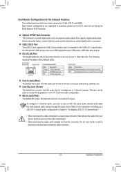
...audio in devices such as a USB keyboard/mouse, USB printer, USB flash drive and etc. Use this audio jack for the Onboard Graphics: This motherboard provides three video output ports: D-Sub, DVI-D, and HDMI. Dual Monitor Configurations for a headphone or 2-channel speaker. Before using this port for ...Optical S/PDIF Out Connector This connector provides digital audio out to an external audio system that your device and then remove it from the motherboard. • When removing the cable, pull it side to side to use an HD front panel audio module and enable the multi-channel...
...audio in devices such as a USB keyboard/mouse, USB printer, USB flash drive and etc. Use this audio jack for the Onboard Graphics: This motherboard provides three video output ports: D-Sub, DVI-D, and HDMI. Dual Monitor Configurations for a headphone or 2-channel speaker. Before using this port for ...Optical S/PDIF Out Connector This connector provides digital audio out to an external audio system that your device and then remove it from the motherboard. • When removing the cable, pull it side to side to use an HD front panel audio module and enable the multi-channel...
Manual
Page 22
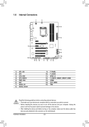
... and your devices are compliant with the connectors you wish to connect. •• Before installing the devices, be sure to the connector on the motherboard. 1-8 Internal Connectors 1 3 5 2 6 7 8 14 10 9 11 13 15 4 12 4 12 1) ATX_12V 2) ATX 3) CPU_FAN 4) SYS_FAN1/2 5) PWR_FAN 6) BAT 7) SATA3_0/1 8) SATA2_2/3/4/5 9) F_PANEL 10) F_AUDIO 11) SPDIF_O 12) F_USB1/F_USB2...
... and your devices are compliant with the connectors you wish to connect. •• Before installing the devices, be sure to the connector on the motherboard. 1-8 Internal Connectors 1 3 5 2 6 7 8 14 10 9 11 13 15 4 12 4 12 1) ATX_12V 2) ATX 3) CPU_FAN 4) SYS_FAN1/2 5) PWR_FAN 6) BAT 7) SATA3_0/1 8) SATA2_2/3/4/5 9) F_PANEL 10) F_AUDIO 11) SPDIF_O 12) F_USB1/F_USB2...
Manual
Page 23
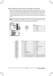
... power connector possesses a foolproof design. Connect the power supply cable to the CPU. If a power supply is turned off and all the components on the motherboard. The 12V power connector mainly supplies power to the power connector in the correct orientation. Hardware Installation Before connecting the power connector, first make sure...
... power connector possesses a foolproof design. Connect the power supply cable to the CPU. If a power supply is turned off and all the components on the motherboard. The 12V power connector mainly supplies power to the power connector in the correct orientation. Hardware Installation Before connecting the power connector, first make sure...


