
Manual
Page 1
GA-X58A-UD9 LGA1366 socket motherboard for Intel® Core™ i7 processor family User's Manual Rev. 1001 12ME-X58AUD9-1001R
GA-X58A-UD9 LGA1366 socket motherboard for Intel® Core™ i7 processor family User's Manual Rev. 1001 12ME-X58AUD9-1001R

Manual
Page 2
Motherboard GA-X58A-UD9 Apr. 12, 2010 Motherboard GA-X58A-UD9 Apr. 12, 2010
Motherboard GA-X58A-UD9 Apr. 12, 2010 Motherboard GA-X58A-UD9 Apr. 12, 2010

Manual
Page 3
... Installation Guide included with the product. All rights reserved. Disclaimer Information in the use GIGABYTE's unique features, read or download the information on/from the Support&Downloads\Motherboard\Technology Guide page on our website. Documentation Classifications In order to the specifications and features...by copyright laws and is 1.0. For product-related information, check on our website at: http://www.gigabyte.com.tw Identifying Your Motherboard Revision The revision number on how to their respective owners. For example, "REV: 1.0" means the revision of the...
... Installation Guide included with the product. All rights reserved. Disclaimer Information in the use GIGABYTE's unique features, read or download the information on/from the Support&Downloads\Motherboard\Technology Guide page on our website. Documentation Classifications In order to the specifications and features...by copyright laws and is 1.0. For product-related information, check on our website at: http://www.gigabyte.com.tw Identifying Your Motherboard Revision The revision number on how to their respective owners. For example, "REV: 1.0" means the revision of the...

Manual
Page 4
Table of Contents Box Contents...6 Optional Items...6 GA-X58A-UD9 Motherboard Layout 7 GA-X58A-UD9 Motherboard Block Diagram 8 Chapter 1 Hardware Installation 9 1-1 Installation Precautions 9 1-2 Product Specifications 10 1-3 Installing the CPU and CPU Cooler 13 1-3-1 Installing the CPU 13 1-3-2 Installing the CPU Cooler ...
Table of Contents Box Contents...6 Optional Items...6 GA-X58A-UD9 Motherboard Layout 7 GA-X58A-UD9 Motherboard Block Diagram 8 Chapter 1 Hardware Installation 9 1-1 Installation Precautions 9 1-2 Product Specifications 10 1-3 Installing the CPU and CPU Cooler 13 1-3-1 Installing the CPU 13 1-3-2 Installing the CPU Cooler ...

Manual
Page 6
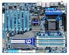
... bracket (Part No. 12CF1-1IE008-0*R) 2-port SATA power cable (Part No. 12CF1-2SERPW-0*R) S/PDIF In cable (Part No. 12CR1-1SPDIN-0*R) - 6 - Box Contents GA-X58A-UD9 motherboard Motherboard driver disk User's Manual Quick Installation Guide One IDE cable Four SATA 3Gb/s cables One SATA bracket I/O Shield One Hybrid Silent-Pipe module kit One...Way SLI bridge connector Two 2-Way CrossFireX bridge connectors • The box contents above are subject to change without notice. • The motherboard image is for reference only and the actual items shall depend on the product package you obtain.
... bracket (Part No. 12CF1-1IE008-0*R) 2-port SATA power cable (Part No. 12CF1-2SERPW-0*R) S/PDIF In cable (Part No. 12CR1-1SPDIN-0*R) - 6 - Box Contents GA-X58A-UD9 motherboard Motherboard driver disk User's Manual Quick Installation Guide One IDE cable Four SATA 3Gb/s cables One SATA bracket I/O Shield One Hybrid Silent-Pipe module kit One...Way SLI bridge connector Two 2-Way CrossFireX bridge connectors • The box contents above are subject to change without notice. • The motherboard image is for reference only and the actual items shall depend on the product package you obtain.

Manual
Page 7
LED PW_SW ATX RST_SW PHASE LED DDR Voltage LED PWR_FAN GA-X58A-UD9 DDR3_2 USB30_LAN JMicron JMB362 AUDIO F_AUDIO SPDIF_I NEC D720200F1 PCIE_12V_1 NF200 RTL8111E NB_FAN Intel® X58 NB TEMP L1/2 NB ...SYS_FAN1 PCIEX16_4 NF200 GIGABYTE SATA2 M_BIOS B_BIOS Intel® ICH10R TSB43AB23 SB Voltage L1/2/3 Debug BAT LED (Note) F_USB3 F_USB2 F_USB1 SYS_FAN2 F_PANEL GSATA2_9 GSATA2_8 SATA2_1 SATA2_0 SATA2_3 SATA2_2 SATA2_5 SATA2_4 PCIE_12V_2 FDD F_1394 SYS_FAN3 (Note) For error code information, please refer to Chapter 5. - 7 - GA-X58A-UD9 Motherboard Layout KB_MS ...
LED PW_SW ATX RST_SW PHASE LED DDR Voltage LED PWR_FAN GA-X58A-UD9 DDR3_2 USB30_LAN JMicron JMB362 AUDIO F_AUDIO SPDIF_I NEC D720200F1 PCIE_12V_1 NF200 RTL8111E NB_FAN Intel® X58 NB TEMP L1/2 NB ...SYS_FAN1 PCIEX16_4 NF200 GIGABYTE SATA2 M_BIOS B_BIOS Intel® ICH10R TSB43AB23 SB Voltage L1/2/3 Debug BAT LED (Note) F_USB3 F_USB2 F_USB1 SYS_FAN2 F_PANEL GSATA2_9 GSATA2_8 SATA2_1 SATA2_0 SATA2_3 SATA2_2 SATA2_5 SATA2_4 PCIE_12V_2 FDD F_1394 SYS_FAN3 (Note) For error code information, please refer to Chapter 5. - 7 - GA-X58A-UD9 Motherboard Layout KB_MS ...
Manual
Page 8
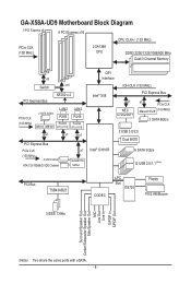
GA-X58A-UD9 Motherboard Block Diagram 3 PCI Express x8 4 PCI Express x16 CPU CLK+/- (133 MHz) PCIe CLK (100 MHz) LGA1366 CPU DDR3 2200/1333/1066/800 MHz Dual/3 ... RTL8111E LAN2 RJ45 Realtek RTL8111E x1 x1 x1 PCI Express Bus PCIe CLK (100 MHz) 2 SATA 3Gb/s ATA-133/100/66/33 IDE Channel x1 GIGABYTE SATA2 QPI Interface IOH CLK (133 MHz) Intel® X58 PCI Express Bus x1 NEC D720200F1 x1 PCIe CLK Marvell 9128 (100 MHz) 2 SATA 6Gb...
GA-X58A-UD9 Motherboard Block Diagram 3 PCI Express x8 4 PCI Express x16 CPU CLK+/- (133 MHz) PCIe CLK (100 MHz) LGA1366 CPU DDR3 2200/1333/1066/800 MHz Dual/3 ... RTL8111E LAN2 RJ45 Realtek RTL8111E x1 x1 x1 PCI Express Bus PCIe CLK (100 MHz) 2 SATA 3Gb/s ATA-133/100/66/33 IDE Channel x1 GIGABYTE SATA2 QPI Interface IOH CLK (133 MHz) Intel® X58 PCI Express Bus x1 NEC D720200F1 x1 PCIe CLK Marvell 9128 (100 MHz) 2 SATA 6Gb...
Manual
Page 9
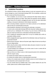
... process can become damaged as a result of electrostatic discharge (ESD). Hardware Installation Chapter 1 Hardware Installation 1-1 Installation Precautions The motherboard contains numerous delicate electronic circuits and components which can lead to damage to system components as well as physical harm to the ...an ESD wrist strap, keep your hands dry and first touch a metal object to eliminate static electricity. • Prior to installing the motherboard, please have a problem related to the use of the product, please consult a certified computer technician. - 9 - These stickers are ...
... process can become damaged as a result of electrostatic discharge (ESD). Hardware Installation Chapter 1 Hardware Installation 1-1 Installation Precautions The motherboard contains numerous delicate electronic circuits and components which can lead to damage to system components as well as physical harm to the ...an ESD wrist strap, keep your hands dry and first touch a metal object to eliminate static electricity. • Prior to installing the motherboard, please have a problem related to the use of the product, please consult a certified computer technician. - 9 - These stickers are ...
Manual
Page 12
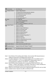
...-ATX Form Factor; 34.5cm x 26.2cm (Note 1) Due to install it is recommended that you install. (Note 5) Available functions in EasyTune may differ by motherboard model. I/O Controller w Hardware Monitor w w w w w w BIOS w w w w Unique Features w w w w w w w w w w w w w Bundled Software w iTE IT8720 chip System voltage detection CPU/System/North Bridge temperature detection CPU/System/Power fan...
...-ATX Form Factor; 34.5cm x 26.2cm (Note 1) Due to install it is recommended that you install. (Note 5) Available functions in EasyTune may differ by motherboard model. I/O Controller w Hardware Monitor w w w w w w BIOS w w w w Unique Features w w w w w w w w w w w w w Bundled Software w iTE IT8720 chip System voltage detection CPU/System/North Bridge temperature detection CPU/System/Power fan...
Manual
Page 13
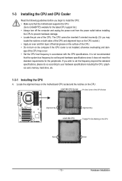
... and unplug the power cord from the power outlet before you begin to install the CPU: • Make sure that the motherboard supports the CPU. (Go to GIGABYTE's website for the latest CPU support list.) • Always turn on the computer if the CPU cooler is not recommended that...(Or you wish to set beyond hardware specifications since it does not meet the standard requirements for the peripherals. Locate the alignment keys on the motherboard CPU socket and the notches on the CPU Notch Notch - 13 - 1-3 Installing the CPU and CPU Cooler Read the following guidelines before installing...
... and unplug the power cord from the power outlet before you begin to install the CPU: • Make sure that the motherboard supports the CPU. (Go to GIGABYTE's website for the latest CPU support list.) • Always turn on the computer if the CPU cooler is not recommended that...(Or you wish to set beyond hardware specifications since it does not meet the standard requirements for the peripherals. Locate the alignment keys on the motherboard CPU socket and the notches on the CPU Notch Notch - 13 - 1-3 Installing the CPU and CPU Cooler Read the following guidelines before installing...
Manual
Page 14
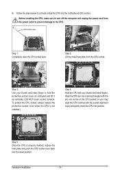
..., always replace the protective socket cover when the CPU is properly inserted, replace the load plate and push the CPU socket lever back into the motherboard CPU socket. Hardware Installation - 14 - CPU Socket Lever Step 1: Completely raise the CPU socket lever. Step 3: Use your thumb and index fingers. Align the CPU...
..., always replace the protective socket cover when the CPU is properly inserted, replace the load plate and push the CPU socket lever back into the motherboard CPU socket. Hardware Installation - 14 - CPU Socket Lever Step 1: Completely raise the CPU socket lever. Step 3: Use your thumb and index fingers. Align the CPU...
Manual
Page 15
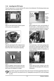
... Installation Step 4: You should hear a "click" when pushing down on the surface of arrow is to remove the cooler, on the motherboard. Use extreme care when removing the CPU cooler because the thermal grease/tape between the CPU cooler and CPU may damage the CPU. - 15 - 1-3-2 ...Installing the CPU Cooler Follow the steps below to correctly install the CPU cooler on the motherboard. (The following procedure uses Intel® boxed cooler as the picture above shows, the installation is to install.) Step 3: Place the cooler atop the CPU...
... Installation Step 4: You should hear a "click" when pushing down on the surface of arrow is to remove the cooler, on the motherboard. Use extreme care when removing the CPU cooler because the thermal grease/tape between the CPU cooler and CPU may damage the CPU. - 15 - 1-3-2 ...Installing the CPU Cooler Follow the steps below to correctly install the CPU cooler on the motherboard. (The following procedure uses Intel® boxed cooler as the picture above shows, the installation is to install.) Step 3: Place the cooler atop the CPU...
Manual
Page 16
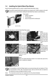
...back panel with a screw to complete the installation. (Note) For the waterblocks on the North Bridge heatsink, we recommend tubes with the motherboard Hybrid Silent-Pipe Follow the steps below to install the Hybrid Silent-Pipe module: Step 1: Apply an even thin layer of thermal grease on... securely and tightly and there is no leak. The components received may vary in appearance from your chassis to the F_AUDIO connector on the motherboard, be sure to connect the front audio module from the products illustrated. Tools needed: 1. Step 4: The picture on the surface of 10mm...
...back panel with a screw to complete the installation. (Note) For the waterblocks on the North Bridge heatsink, we recommend tubes with the motherboard Hybrid Silent-Pipe Follow the steps below to install the Hybrid Silent-Pipe module: Step 1: Apply an even thin layer of thermal grease on... securely and tightly and there is no leak. The components received may vary in appearance from your chassis to the F_AUDIO connector on the motherboard, be sure to connect the front audio module from the products illustrated. Tools needed: 1. Step 4: The picture on the surface of 10mm...
Manual
Page 17
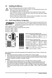
...the same capacity, brand, speed, and chips be sure to insert the memory, switch the direction. 1-5-1 Dual/3 Channel Memory Configuration This motherboard provides six DDR3 memory sockets and supports Dual/3 Channel Technology. The six DDR3 memory sockets are unable to install them in the DDR3_1, .../SS - - When enabling 3 Channel mode with three memory modules, be used . After the memory is installed, be used . (Go to GIGABYTE's website for the latest supported memory speeds and momery moudles.) • Always turn off the computer and unplug the power cord from the power outlet...
...the same capacity, brand, speed, and chips be sure to insert the memory, switch the direction. 1-5-1 Dual/3 Channel Memory Configuration This motherboard provides six DDR3 memory sockets and supports Dual/3 Channel Technology. The six DDR3 memory sockets are unable to install them in the DDR3_1, .../SS - - When enabling 3 Channel mode with three memory modules, be used . After the memory is installed, be used . (Go to GIGABYTE's website for the latest supported memory speeds and momery moudles.) • Always turn off the computer and unplug the power cord from the power outlet...
Manual
Page 18
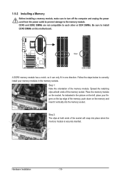
..., make sure to turn off the computer and unplug the power cord from the power outlet to prevent damage to install DDR3 DIMMs on this motherboard. Step 1: Note the orientation of the socket will snap into the memory socket. Notch DDR3 DIMM A DDR3 memory module has a notch, so it vertically into...
..., make sure to turn off the computer and unplug the power cord from the power outlet to prevent damage to install DDR3 DIMMs on this motherboard. Step 1: Note the orientation of the socket will snap into the memory socket. Notch DDR3 DIMM A DDR3 memory module has a notch, so it vertically into...

Manual
Page 19
... computer. Make sure the card is fully inserted into the slot. 4. Secure the card's metal bracket to install an expansion card: • Make sure the motherboard supports the expansion card. 1-6 Installing an Expansion Card Read the following guidelines before installing an expansion card to release the card and then pull the...
... computer. Make sure the card is fully inserted into the slot. 4. Secure the card's metal bracket to install an expansion card: • Make sure the motherboard supports the expansion card. 1-6 Installing an Expansion Card Read the following guidelines before installing an expansion card to release the card and then pull the...
Manual
Page 20
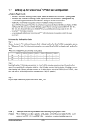
... of the graphics cards in the CrossFireX/SLI gold edge connectors on the PCIEX16_1 slot. (Note 1) (Note 2) The bridge connectors may occur. A CrossFireX/SLI-supported motherboard with two/three/four cards. Two/three/four CrossFireX/SLI-ready graphics cards of the two/three/four cards. (To set up ATI CrossFireX™...
... of the graphics cards in the CrossFireX/SLI gold edge connectors on the PCIEX16_1 slot. (Note 1) (Note 2) The bridge connectors may occur. A CrossFireX/SLI-supported motherboard with two/three/four cards. Two/three/four CrossFireX/SLI-ready graphics cards of the two/three/four cards. (To set up ATI CrossFireX™...
Manual
Page 22
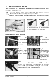
... with a screw. Step 5: Connect the other ends of the SATA signal cable and SATA power cable to your system and the power switch on your motherboard. Hardware Installation - 22 - Then attach the SATA power cable to the power connector on the bracket. 1-8 Installing the SATA Bracket The SATA bracket allows you...
... with a screw. Step 5: Connect the other ends of the SATA signal cable and SATA power cable to your system and the power switch on your motherboard. Hardware Installation - 22 - Then attach the SATA power cable to the power connector on the bracket. 1-8 Installing the SATA Bracket The SATA bracket allows you...
Manual
Page 23
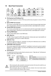
... etc. Optical S/PDIF Out Connector This connector provides digital audio out to an external audio system that your device and then remove it from the motherboard. • When removing the cable, pull it side to side to clear CMOS values. USB 2.0/1.1 Port The USB port supports the USB 2.0/1.1 specification. Do not...
... etc. Optical S/PDIF Out Connector This connector provides digital audio out to an external audio system that your device and then remove it from the motherboard. • When removing the cable, pull it side to side to clear CMOS values. USB 2.0/1.1 Port The USB port supports the USB 2.0/1.1 specification. Do not...
Manual
Page 25
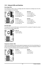
Hardware Installation the red LED is below 60oC; 1-10 Onboard LEDs and Switches Overvoltage LEDs This motherboard contains 4 sets of overvoltage LEDs which level the CPU is overclocked. The LEDs are off when the temperature is illuminated when the temperature exceeds 80oC. ...
Hardware Installation the red LED is below 60oC; 1-10 Onboard LEDs and Switches Overvoltage LEDs This motherboard contains 4 sets of overvoltage LEDs which level the CPU is overclocked. The LEDs are off when the temperature is illuminated when the temperature exceeds 80oC. ...


