
Manual
Page 1
...system for complex and time-consuming configurations. All with which you have to load the SATA controller driver first. B. Using GIGABYTE eXtreme Hard Drive (X.H.D) Instructions:(Note 2) Before launching X.H.D, make sure the new drive is recommended that 's been created ... the X.H.D utility. (Note 1) The X.H.D utility only supports the SATA controllers integrated in the array. ) 1. eXtreme Hard Drive (X.H.D) With GIGABYTE eXtreme Hard Drive (X.H.D)(Note 1), users can go to the Application Software screen to automatically set up a RAID 0 array later using the Auto function...
...system for complex and time-consuming configurations. All with which you have to load the SATA controller driver first. B. Using GIGABYTE eXtreme Hard Drive (X.H.D) Instructions:(Note 2) Before launching X.H.D, make sure the new drive is recommended that 's been created ... the X.H.D utility. (Note 1) The X.H.D utility only supports the SATA controllers integrated in the array. ) 1. eXtreme Hard Drive (X.H.D) With GIGABYTE eXtreme Hard Drive (X.H.D)(Note 1), users can go to the Application Software screen to automatically set up a RAID 0 array later using the Auto function...

Manual
Page 1
GA-P55M-UD4 LGA1156 socket motherboard for Intel® Core™ i7 processor family/ Intel® Core™ i5 processor family User's Manual Rev. 1001 12ME-P55MUD4-1001R
GA-P55M-UD4 LGA1156 socket motherboard for Intel® Core™ i7 processor family/ Intel® Core™ i5 processor family User's Manual Rev. 1001 12ME-P55MUD4-1001R

Manual
Page 3
...; 2009 GIGA-BYTE TECHNOLOGY CO., LTD. For example, "REV: 1.0" means the revision of the motherboard is the property of GIGABYTE. No part of the product, read or download the information on/from the Support&Downloads\Motherboard\Technology Guide page on your motherboard ...revision before updating motherboard BIOS, drivers, or when looking for technical information. Documentation Classifications In order to use of this product, GIGABYTE provides the following types of documentations: For quick set-up of this manual may be reproduced, copied, translated, transmitted, or...
...; 2009 GIGA-BYTE TECHNOLOGY CO., LTD. For example, "REV: 1.0" means the revision of the motherboard is the property of GIGABYTE. No part of the product, read or download the information on/from the Support&Downloads\Motherboard\Technology Guide page on your motherboard ...revision before updating motherboard BIOS, drivers, or when looking for technical information. Documentation Classifications In order to use of this product, GIGABYTE provides the following types of documentations: For quick set-up of this manual may be reproduced, copied, translated, transmitted, or...

Manual
Page 4
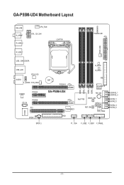
Table of Contents Box Contents...6 Optional Items...6 GA-P55M-UD4 Motherboard Layout 7 Block Diagram...8 Chapter 1 Hardware Installation 9 1-1 Installation Precautions 9 1-2 Product Specifications 10 1-3 Installing the CPU and CPU Cooler 13 1-3-1 Installing the CPU 13 1-3-2 Installing the ...
Table of Contents Box Contents...6 Optional Items...6 GA-P55M-UD4 Motherboard Layout 7 Block Diagram...8 Chapter 1 Hardware Installation 9 1-1 Installation Precautions 9 1-2 Product Specifications 10 1-3 Installing the CPU and CPU Cooler 13 1-3-1 Installing the CPU 13 1-3-2 Installing the ...
Manual
Page 5
... 4-4 Dynamic Energy Saver™ 2 73 4-5 Q-Share...75 4-6 Smart 6™ ...76 Chapter 5 Appendix...79 5-1 Configuring SATA Hard Drive(s 79 5-1-1 Configuring Intel P55 SATA Controllers 79 5-1-2 Configuring GIGABYTE SATA2 SATA Controller 87 5-1-3 Making a SATA RAID/AHCI Driver Diskette 93 5-1-4 Installing the SATA RAID/AHCI Driver and Operating System 94 5-2 Configuring Audio Input and...
... 4-4 Dynamic Energy Saver™ 2 73 4-5 Q-Share...75 4-6 Smart 6™ ...76 Chapter 5 Appendix...79 5-1 Configuring SATA Hard Drive(s 79 5-1-1 Configuring Intel P55 SATA Controllers 79 5-1-2 Configuring GIGABYTE SATA2 SATA Controller 87 5-1-3 Making a SATA RAID/AHCI Driver Diskette 93 5-1-4 Installing the SATA RAID/AHCI Driver and Operating System 94 5-2 Configuring Audio Input and...

Manual
Page 6
The box contents are for reference only. Box Contents GA-P55M-UD4 motherboard Motherboard driver disk User's Manual Quick Installation Guide One IDE cable Four SATA 3Gb/s cables I/O Shield 2-Way SLI bridge connector • The box contents ...
The box contents are for reference only. Box Contents GA-P55M-UD4 motherboard Motherboard driver disk User's Manual Quick Installation Guide One IDE cable Four SATA 3Gb/s cables I/O Shield 2-Way SLI bridge connector • The box contents ...
Manual
Page 7
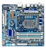
GA-P55M-UD4 Motherboard Layout KB_USB R_SPDIF R_USB_2 CPU_FAN ATX_12V_2X4 LGA1156 PHASE LED ATX PWR_FAN R_USB_1 USB_1394_ESATA USB_LAN RTL8111D AUDIO F_AUDIO SYS_FAN1 CODEC PCIEX4 CD_IN PCIEX8 PCI IT8720 SPDIF_O SPDIF_I B_BIOS M_BIOS BAT PCIEX16 GA-P55M-UD4 DDR3_2 DDR3_1 DDR3_4 DDR3_3 IDE GIGABYTE SATA2 PW_SW TSB43AB23 Intel® P55 CMOS_SW SATA2_4 RST_SW SYS_FAN2 FDD GSATA2_1 GSATA2_0 SATA2_1 SATA2_0 SATA2_3 SATA2_2 F1_1394 F_USB2 F_USB1 F_PANEL - 7 -
GA-P55M-UD4 Motherboard Layout KB_USB R_SPDIF R_USB_2 CPU_FAN ATX_12V_2X4 LGA1156 PHASE LED ATX PWR_FAN R_USB_1 USB_1394_ESATA USB_LAN RTL8111D AUDIO F_AUDIO SYS_FAN1 CODEC PCIEX4 CD_IN PCIEX8 PCI IT8720 SPDIF_O SPDIF_I B_BIOS M_BIOS BAT PCIEX16 GA-P55M-UD4 DDR3_2 DDR3_1 DDR3_4 DDR3_3 IDE GIGABYTE SATA2 PW_SW TSB43AB23 Intel® P55 CMOS_SW SATA2_4 RST_SW SYS_FAN2 FDD GSATA2_1 GSATA2_0 SATA2_1 SATA2_0 SATA2_3 SATA2_2 F1_1394 F_USB2 F_USB1 F_PANEL - 7 -
Manual
Page 8
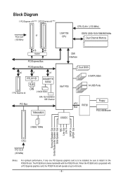
...+/- (133 MHz) DDR3 2200/1333/1066/800 MHz Dual Channel Memory x16 x8 Switch PCI Express Bus PCI Express Bus x4 x1 x1 RTL8111D RJ45 GIGABYTE SATA2 1 PCI Express x4 LAN 2 SATA 3Gb/s ATA-133/100/66/33 IDE Channel PCI Bus TSB43AB23 DMI Interface Intel® P55 Dual BIOS 6 SATA...
...+/- (133 MHz) DDR3 2200/1333/1066/800 MHz Dual Channel Memory x16 x8 Switch PCI Express Bus PCI Express Bus x4 x1 x1 RTL8111D RJ45 GIGABYTE SATA2 1 PCI Express x4 LAN 2 SATA 3Gb/s ATA-133/100/66/33 IDE Channel PCI Bus TSB43AB23 DMI Interface Intel® P55 Dual BIOS 6 SATA...

Manual
Page 9
Prior to installation, carefully read the user's manual and follow these procedures: • Prior to the use of electrostatic discharge (ESD). ponents such as a result of the product, please consult a certified computer technician. - 9 - Hardware Installation If you are connected tightly and securely. • When handling the motherboard, avoid touching any installation steps or have it on top of your dealer. Chapter 1 Hardware Installation 1-1 Installation Precautions The motherboard contains numerous delicate electronic circuits and components which can lead to ...
Prior to installation, carefully read the user's manual and follow these procedures: • Prior to the use of electrostatic discharge (ESD). ponents such as a result of the product, please consult a certified computer technician. - 9 - Hardware Installation If you are connected tightly and securely. • When handling the motherboard, avoid touching any installation steps or have it on top of your dealer. Chapter 1 Hardware Installation 1-1 Installation Precautions The motherboard contains numerous delicate electronic circuits and components which can lead to ...

Manual
Page 10
... Support for an Intel® Core™ i7 series processor/Intel® Core™ i5 series processor in the LGA1156 package (Go to GIGABYTE's website for the latest CPU support list.) L3 cache varies with CPU Chipset w Intel® P55 Express Chipset Memory Audio 4 .../800 MHz memory modules Support for non-ECC memory modules Support for Extreme Memory Profile (XMP) memory modules (Go to GIGABYTE's website for the latest memory support list.) Realtek ALC889A codec High Definition Audio 2/4/5.1/7.1-channel w Support for Dolby&#...
... Support for an Intel® Core™ i7 series processor/Intel® Core™ i5 series processor in the LGA1156 package (Go to GIGABYTE's website for the latest CPU support list.) L3 cache varies with CPU Chipset w Intel® P55 Express Chipset Memory Audio 4 .../800 MHz memory modules Support for non-ECC memory modules Support for Extreme Memory Profile (XMP) memory modules (Go to GIGABYTE's website for the latest memory support list.) Realtek ALC889A codec High Definition Audio 2/4/5.1/7.1-channel w Support for Dolby&#...

Manual
Page 11
Hardware Installation TSB43AB23 chip Up to 2 IEEE 1394a ports (1 on the back panel, including 1 eSATA/USB Combo, 4 via the IEEE 1394a bracket connected to the internal USB headers) T.I /O Controller w iTE IT8720 chip Hardware Monitor w w w w w w System voltage detection CPU/System temperature detection CPU/System/Power fan speed detection CPU overheating warning CPU/System/Power fan fail warning CPU/System fan speed control (Note 4) - 11 - USB w IEEE 1394 w Internal w Connectors w w w w w w w...
Hardware Installation TSB43AB23 chip Up to 2 IEEE 1394a ports (1 on the back panel, including 1 eSATA/USB Combo, 4 via the IEEE 1394a bracket connected to the internal USB headers) T.I /O Controller w iTE IT8720 chip Hardware Monitor w w w w w w System voltage detection CPU/System temperature detection CPU/System/Power fan speed detection CPU overheating warning CPU/System/Power fan fail warning CPU/System fan speed control (Note 4) - 11 - USB w IEEE 1394 w Internal w Connectors w w w w w w w...

Manual
Page 12
BIOS w w w w Unique Features w w w w w w w w w w Bundled Software w 2 x 16 Mbit flash Use of licensed AWARD BIOS Support for DualBIOS™ PnP 1.0a, DMI 2.0, SM BIOS 2.4, ACPI 1.0b Support for @BIOS Support for Q-Flash Support for Xpress BIOS Rescue Support for Download Center Support for Xpress Install Support for Xpress Recovery2 Support for EasyTune (Note 5) Support for Dynamic Energy Saver™ 2 Support for Smart 6™ Support for Q-Share Norton Internet Security (OEM version) Operating System w Support...
BIOS w w w w Unique Features w w w w w w w w w w Bundled Software w 2 x 16 Mbit flash Use of licensed AWARD BIOS Support for DualBIOS™ PnP 1.0a, DMI 2.0, SM BIOS 2.4, ACPI 1.0b Support for @BIOS Support for Q-Flash Support for Xpress BIOS Rescue Support for Download Center Support for Xpress Install Support for Xpress Recovery2 Support for EasyTune (Note 5) Support for Dynamic Energy Saver™ 2 Support for Smart 6™ Support for Q-Share Norton Internet Security (OEM version) Operating System w Support...

Manual
Page 13
... Corner of the CPU. • Do not turn off the computer and unplug the power cord from the power outlet before installing the CPU to GIGABYTE's website for the peripherals. Hardware Installation The CPU cannot be set the frequency beyond hardware specifications since it does not meet the standard requirements for...
... Corner of the CPU. • Do not turn off the computer and unplug the power cord from the power outlet before installing the CPU to GIGABYTE's website for the peripherals. Hardware Installation The CPU cannot be set the frequency beyond hardware specifications since it does not meet the standard requirements for...

Manual
Page 14
Then completely lift the CPU socket lever and the metal load plate will be lifted as indicated and lift it up vertically. (DO NOT touch socket contacts. Align the CPU pin one marking (triangle) with the pin one corner of the load plate is properly inserted, use one hand to hold the socket lever and use the other to lightly replace the load plate. Step 5: Push the CPU socket lever back into position. Before installing the CPU, make sure the front end of the CPU socket (or you may align the CPU notches with the socket alignment keys) and gently insert the CPU into its locked position. ...
Then completely lift the CPU socket lever and the metal load plate will be lifted as indicated and lift it up vertically. (DO NOT touch socket contacts. Align the CPU pin one marking (triangle) with the pin one corner of the load plate is properly inserted, use one hand to hold the socket lever and use the other to lightly replace the load plate. Step 5: Push the CPU socket lever back into position. Before installing the CPU, make sure the front end of the CPU socket (or you may align the CPU notches with the socket alignment keys) and gently insert the CPU into its locked position. ...

Manual
Page 15
If the push pin is inserted as the example cooler.) Step 1: Apply an even and thin layer of thermal grease on the surface of the installed CPU. Inadequately removing the CPU cooler may adhere to the CPU fan header (CPU_FAN) on the motherboard. Push down each push pin. Check that the Male and Female push pins are joined closely. (Refer to correctly install the CPU cooler on the motherboard. (The following procedure uses Intel® boxed cooler as the picture above shows, the installation is to install.) Step 3: Place the cooler atop the CPU, aligning the four push pins through...
If the push pin is inserted as the example cooler.) Step 1: Apply an even and thin layer of thermal grease on the surface of the installed CPU. Inadequately removing the CPU cooler may adhere to the CPU fan header (CPU_FAN) on the motherboard. Push down each push pin. Check that the Male and Female push pins are joined closely. (Refer to correctly install the CPU cooler on the motherboard. (The following procedure uses Intel® boxed cooler as the picture above shows, the installation is to install.) Step 3: Place the cooler atop the CPU, aligning the four push pins through...

Manual
Page 16
A memory module can be used . (Go to GIGABYTE's website for optimum performance. After the memory is installed. 2. If you begin to install it in the DDR3_1 or DDR3_3 sockets. DS/SS - - When enabling ...
A memory module can be used . (Go to GIGABYTE's website for optimum performance. After the memory is installed. 2. If you begin to install it in the DDR3_1 or DDR3_3 sockets. DS/SS - - When enabling ...

Manual
Page 17
Follow the steps below to correctly install your fingers on the top edge of the memory socket. Step 2: The clips at both ends of the memory module. 1-4-2 Installing a Memory Before installing a memory module, make sure to turn off the computer and unplug the power cord from the power outlet to prevent damage to install DDR3 DIMMs on the socket. As indicated in the picture on the memory and insert it can only fit in the memory sockets. Notch DDR3 DIMM A DDR3 memory module has a notch, so it vertically into place when the memory module is securely inserted. - 17 - Place the ...
Follow the steps below to correctly install your fingers on the top edge of the memory socket. Step 2: The clips at both ends of the memory module. 1-4-2 Installing a Memory Before installing a memory module, make sure to turn off the computer and unplug the power cord from the power outlet to prevent damage to install DDR3 DIMMs on the socket. As indicated in the picture on the memory and insert it can only fit in the memory sockets. Notch DDR3 DIMM A DDR3 memory module has a notch, so it vertically into place when the memory module is securely inserted. - 17 - Place the ...

Manual
Page 18
Align the card with your expansion card(s). 7. Hardware Installation - 18 - Remove the metal slot cover from the power outlet before you begin to prevent hardware damage. Turn on the top edge of the PCI Express slot to the chassis back panel with the expansion card in your expansion card in the expansion slot. 1. Make sure the card is fully seated in the slot and does not rock. • Removing the Card: Press the white latch at the end of the card until it is fully inserted into the slot. 4. Locate an expansion slot that came with the slot, and press down...
Align the card with your expansion card(s). 7. Hardware Installation - 18 - Remove the metal slot cover from the power outlet before you begin to prevent hardware damage. Turn on the top edge of the PCI Express slot to the chassis back panel with the expansion card in your expansion card in the expansion slot. 1. Make sure the card is fully seated in the slot and does not rock. • Removing the Card: Press the white latch at the end of the card until it is fully inserted into the slot. 4. Locate an expansion slot that came with the slot, and press down...

Manual
Page 19
System Requirements - Two CrossFire (Note)/SLI bridge connectors - C. Configuring the Graphics Card Driver C-1. Refer to the ATI Catalyst Control Center. To Enable CrossFireX Function After installing the graphics card driver in the operating system, go to the manual that came with your graphics cards for more information about enabling CrossFireX/SLI technology. - 19 - C-2. Procedure and driver screen for the power requirement) B. Two CrossFireX/SLI-ready graphics cards of ATI CrossFireX™/NVIDIA SLI Configuration A. Browse to the NVIDIA Control Panel. ...
System Requirements - Two CrossFire (Note)/SLI bridge connectors - C. Configuring the Graphics Card Driver C-1. Refer to the ATI Catalyst Control Center. To Enable CrossFireX Function After installing the graphics card driver in the operating system, go to the manual that came with your graphics cards for more information about enabling CrossFireX/SLI technology. - 19 - C-2. Procedure and driver screen for the power requirement) B. Two CrossFireX/SLI-ready graphics cards of ATI CrossFireX™/NVIDIA SLI Configuration A. Browse to the NVIDIA Control Panel. ...

Manual
Page 20
Use this port for USB devices such as a USB keyboard/mouse, USB printer, USB flash drive and etc. Optical S/PDIF Out Connector This connector provides digital audio out to an external audio system that supports digital coaxial audio. Before using this feature, ensure that your audio system provides an optical digital audio in connector. Use the port to 1 Gbps data rate. RJ-45 LAN Port The Gigabit Ethernet LAN port provides Internet connection at up to connect an external SATA device or a SATA port multiplier; Hardware Installation - 20 - Coaxial S/PDIF Out ...
Use this port for USB devices such as a USB keyboard/mouse, USB printer, USB flash drive and etc. Optical S/PDIF Out Connector This connector provides digital audio out to an external audio system that supports digital coaxial audio. Before using this feature, ensure that your audio system provides an optical digital audio in connector. Use the port to 1 Gbps data rate. RJ-45 LAN Port The Gigabit Ethernet LAN port provides Internet connection at up to connect an external SATA device or a SATA port multiplier; Hardware Installation - 20 - Coaxial S/PDIF Out ...
