Manual
Page 1
GA-P31-ES3G LGA775 socket motherboard for Intel® CoreTM processor family/ Intel® Pentium® processor family/Intel® Celeron® processor family User's Manual Rev. 1101 12ME-P31ES3G-1101R
GA-P31-ES3G LGA775 socket motherboard for Intel® CoreTM processor family/ Intel® Pentium® processor family/Intel® Celeron® processor family User's Manual Rev. 1101 12ME-P31ES3G-1101R
Manual
Page 2
Motherboard GA-P31-ES3G Jul. 24, 2008 Motherboard GA-P31-ES3G Jul. 24, 2008
Motherboard GA-P31-ES3G Jul. 24, 2008 Motherboard GA-P31-ES3G Jul. 24, 2008
Manual
Page 3
...manual is protected by copyright laws and is the property of the motherboard is 1.0. Changes to assist in any means without prior notice. For example, "REV: 1.0" means the revision of GIGABYTE. Check your motherboard looks like this manual may be reproduced, copied, translated, transmitted,... manual may be made by any form or by GIGABYTE without GIGABYTE's prior written permission. All rights reserved. For product-related information, check on our website at: http://www.gigabyte.com.tw Identifying Your Motherboard Revision The revision number on how to their respective ...
...manual is protected by copyright laws and is the property of the motherboard is 1.0. Changes to assist in any means without prior notice. For example, "REV: 1.0" means the revision of GIGABYTE. Check your motherboard looks like this manual may be reproduced, copied, translated, transmitted,... manual may be made by any form or by GIGABYTE without GIGABYTE's prior written permission. All rights reserved. For product-related information, check on our website at: http://www.gigabyte.com.tw Identifying Your Motherboard Revision The revision number on how to their respective ...
Manual
Page 4
Table of Contents Box Contents ...6 OptionalItems ...6 GA-P31-ES3G Motherboard Layout 7 Block Diagram ...8 Chapter 1 Hardware Installation 9 1-1 Installation Precautions 9 1-2 Product Specifications 10 1-3 Installing the CPU and CPU Cooler 13 1-3-1 Installing the CPU 13 1-3-2 Installing the CPU ...
Table of Contents Box Contents ...6 OptionalItems ...6 GA-P31-ES3G Motherboard Layout 7 Block Diagram ...8 Chapter 1 Hardware Installation 9 1-1 Installation Precautions 9 1-2 Product Specifications 10 1-3 Installing the CPU and CPU Cooler 13 1-3-1 Installing the CPU 13 1-3-2 Installing the CPU ...
Manual
Page 6
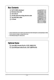
Optional Items 2-port USB 2.0 bracket (Part No. 12CR1-1UB030-51R) 2-port SATA power cable (Part No. 12CF1-2SERPW-01R) - 6 - The box contents are for reference only. Box Contents GA-P31-ES3G motherboard Motherboard driver disk User's Manual One IDE cable and one floppy disk drive cable Two SATA 3Gb/s cables I/O Shield • The box contents above are subject to change without notice. • The motherboard image is for reference only and the actual items shall depend on product package you obtain.
Optional Items 2-port USB 2.0 bracket (Part No. 12CR1-1UB030-51R) 2-port SATA power cable (Part No. 12CF1-2SERPW-01R) - 6 - The box contents are for reference only. Box Contents GA-P31-ES3G motherboard Motherboard driver disk User's Manual One IDE cable and one floppy disk drive cable Two SATA 3Gb/s cables I/O Shield • The box contents above are subject to change without notice. • The motherboard image is for reference only and the actual items shall depend on product package you obtain.
Manual
Page 7
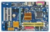
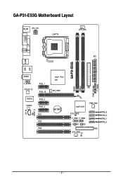
GA-P31-ES3G Motherboard Layout KB_MS ATX_12V LGA775 CPU_FAN COMA LPT COAXIAL ATX GA-P31-ES3G USB R_USB LAN AUDIO F_AUDIO RTL8111C IT8718 CODEC PCIE_1 PCIE_16 PCIE_2 PCIE_3 CD_IN SPDIF_O PCI1 PCI2 PCI3 PWR_LED F_PANEL Intel® P31/ G31 IDE SYS_FAN1 DDRII1 DDRII2 BATTERY Intel® ICH7 PWR_FAN CLR_CMOS F_USB1 F_USB2 M_BIOS B_BIOS SYS_FAN2 CI SATA2_3 SATA2_2 SATA2_1 SATA2_0 FDD - 7 -
GA-P31-ES3G Motherboard Layout KB_MS ATX_12V LGA775 CPU_FAN COMA LPT COAXIAL ATX GA-P31-ES3G USB R_USB LAN AUDIO F_AUDIO RTL8111C IT8718 CODEC PCIE_1 PCIE_16 PCIE_2 PCIE_3 CD_IN SPDIF_O PCI1 PCI2 PCI3 PWR_LED F_PANEL Intel® P31/ G31 IDE SYS_FAN1 DDRII1 DDRII2 BATTERY Intel® ICH7 PWR_FAN CLR_CMOS F_USB1 F_USB2 M_BIOS B_BIOS SYS_FAN2 CI SATA2_3 SATA2_2 SATA2_1 SATA2_0 FDD - 7 -

Manual
Page 9
... damaged as a result of the product, please consult a certified computer technician. - 9 - Chapter 1 Hardware Installation 1-1 Installation Precautions The motherboard contains numerous delicate electronic circuits and components which can lead to damage to system components as well as physical harm to the user. •... or connectors. • It is best to wear an electrostatic discharge (ESD) wrist strap when handling electronic components such as a motherboard, CPU or memory. These stickers are required for warranty validation. • Always remove the AC power by your hands dry and ...
... damaged as a result of the product, please consult a certified computer technician. - 9 - Chapter 1 Hardware Installation 1-1 Installation Precautions The motherboard contains numerous delicate electronic circuits and components which can lead to damage to system components as well as physical harm to the user. •... or connectors. • It is best to wear an electrostatic discharge (ESD) wrist strap when handling electronic components such as a motherboard, CPU or memory. These stickers are required for warranty validation. • Always remove the AC power by your hands dry and ...
Manual
Page 10
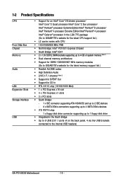
.../Intel® Pentium® 4 processor/ Intel® Celeron® processor in the LGA 775 package (Go to GIGABYTE's website for the latest CPU support list.) Š L2 cache varies with CPU Š 1333/1066/800 MHz FSB &#...memory (Note 1) Š Dual channel memory architecture Š Support for DDR2 1066/800/667 MHz memory modules (Go to GIGABYTE's website for the latest memory support list.) Š Realtek ALC888 codec Š High Definition Audio Š 2/4/5.1/7.1-channel (Note ... the back panel, 4 via the USB brackets connected to the internal USB headers) GA-P31-ES3G Motherboard - 10 -
.../Intel® Pentium® 4 processor/ Intel® Celeron® processor in the LGA 775 package (Go to GIGABYTE's website for the latest CPU support list.) Š L2 cache varies with CPU Š 1333/1066/800 MHz FSB &#...memory (Note 1) Š Dual channel memory architecture Š Support for DDR2 1066/800/667 MHz memory modules (Go to GIGABYTE's website for the latest memory support list.) Š Realtek ALC888 codec Š High Definition Audio Š 2/4/5.1/7.1-channel (Note ... the back panel, 4 via the USB brackets connected to the internal USB headers) GA-P31-ES3G Motherboard - 10 -
Manual
Page 12
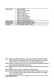
For example, 4 GB of memory is less than the stated amount. GA-P31-ES3G Motherboard - 12 - Unique Features Bundled Software Operating System Form Factor Š Support for @BIOS Š Support for Download Center Š Support for Q-Flash Š Support for ... 3) Whether the CPU fan speed control function is supported will depend on the CPU cooler you install. (Note 4) Available functions in EasyTune may differ by motherboard model. (Note 5) Due to the hardware limitation, you must install the Intel® CoreTM 2 Extreme/ CoreTM 2 Quad/ CoreTM 2 Duo/ Pentium Dual-Core/ Celeron Dual-...
For example, 4 GB of memory is less than the stated amount. GA-P31-ES3G Motherboard - 12 - Unique Features Bundled Software Operating System Form Factor Š Support for @BIOS Š Support for Download Center Š Support for Q-Flash Š Support for ... 3) Whether the CPU fan speed control function is supported will depend on the CPU cooler you install. (Note 4) Available functions in EasyTune may differ by motherboard model. (Note 5) Due to the hardware limitation, you must install the Intel® CoreTM 2 Extreme/ CoreTM 2 Quad/ CoreTM 2 Duo/ Pentium Dual-Core/ Celeron Dual-...

Manual
Page 13
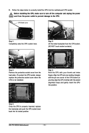
... the computer and unplug the power cord from the power outlet before you begin to install the CPU: • Make sure that the motherboard supports the CPU. (Go to GIGABYTE's website for the peripherals. Hardware Installation mended that the system bus frequency be inserted if oriented incorrectly. (Or you may occur. •...
... the computer and unplug the power cord from the power outlet before you begin to install the CPU: • Make sure that the motherboard supports the CPU. (Go to GIGABYTE's website for the peripherals. Hardware Installation mended that the system bus frequency be inserted if oriented incorrectly. (Or you may occur. •...
Manual
Page 14
... inserted, replace the load plate and push the CPU socket lever back into its locked position. B. Before installing the CPU, make sure to the CPU. GA-P31-ES3G Motherboard - 14 - Step 5: Once the CPU is not installed.) Step 4: Hold the CPU with the socket alignment keys) and gently insert the CPU into the...
... inserted, replace the load plate and push the CPU socket lever back into its locked position. B. Before installing the CPU, make sure to the CPU. GA-P31-ES3G Motherboard - 14 - Step 5: Once the CPU is not installed.) Step 4: Hold the CPU with the socket alignment keys) and gently insert the CPU into the...

Manual
Page 15
Push down each push pin. 1-3-2 Installing the CPU Cooler Follow the steps below to correctly install the CPU cooler on the motherboard. (The following procedure uses Intel® boxed cooler as the picture above, the installation is complete. Use extreme care when removing the CPU cooler because... of arrow is to remove the cooler, on the contrary, is inserted as the example cooler.) Step 1: Apply an even and thin layer of the motherboard. Check that the Male and Female push pins are joined closely. (Refer to install.) Step 3: Place the cooler atop the CPU, aligning the four push...
Push down each push pin. 1-3-2 Installing the CPU Cooler Follow the steps below to correctly install the CPU cooler on the motherboard. (The following procedure uses Intel® boxed cooler as the picture above, the installation is complete. Use extreme care when removing the CPU cooler because... of arrow is to remove the cooler, on the contrary, is inserted as the example cooler.) Step 1: Apply an even and thin layer of the motherboard. Check that the Male and Female push pins are joined closely. (Refer to install.) Step 3: Place the cooler atop the CPU, aligning the four push...
Manual
Page 16
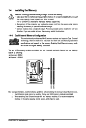
A memory module can be used . (Go to GIGABYTE's website for the latest memory support list.) •... it is installed. 2. Enabling Dual Channel memory mode will automatically detect the specifications and capacity of the memory. GA-P31-ES3G Motherboard - 16 - The two DDR2 memory sockets are unable to install the memory: • Make sure that memory... capacity, brand, speed, and chips be enabled if only one DDR2 memory module is recommended that the motherboard supports the memory. Dual Channel mode cannot be used . 1-4 Installing the Memory Read the following guidelines before...
A memory module can be used . (Go to GIGABYTE's website for the latest memory support list.) •... it is installed. 2. Enabling Dual Channel memory mode will automatically detect the specifications and capacity of the memory. GA-P31-ES3G Motherboard - 16 - The two DDR2 memory sockets are unable to install the memory: • Make sure that memory... capacity, brand, speed, and chips be enabled if only one DDR2 memory module is recommended that the motherboard supports the memory. Dual Channel mode cannot be used . 1-4 Installing the Memory Read the following guidelines before...

Manual
Page 17
... , make sure to turn off the computer and unplug the power cord from the power outlet to prevent damage to install DDR2 DIMMs on this motherboard. Notch DDR2 DIMM A DDR2 memory module has a notch, so it vertically into place when the memory module is securely inserted. - 17...
... , make sure to turn off the computer and unplug the power cord from the power outlet to prevent damage to install DDR2 DIMMs on this motherboard. Notch DDR2 DIMM A DDR2 memory module has a notch, so it vertically into place when the memory module is securely inserted. - 17...
Manual
Page 18
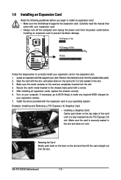
...Express x16 Graphics Card: • Installing a Graphics Card: Gently push down on the card until it is fully inserted into the slot. 4. GA-P31-ES3G Motherboard - 18 - PCI Express x1 Slot PCI Express x16 Slot PCI Slot Follow the steps below to correctly install your expansion card in the slot ... and then lift the card straight out from the power outlet before you begin to install an expansion card: • Make sure the motherboard supports the expansion card. Remove the metal slot cover from the chassis back panel. 2. 1-5 Installing an Expansion Card Read the following guidelines...
...Express x16 Graphics Card: • Installing a Graphics Card: Gently push down on the card until it is fully inserted into the slot. 4. GA-P31-ES3G Motherboard - 18 - PCI Express x1 Slot PCI Express x16 Slot PCI Slot Follow the steps below to correctly install your expansion card in the slot ... and then lift the card straight out from the power outlet before you begin to install an expansion card: • Make sure the motherboard supports the expansion card. Remove the metal slot cover from the chassis back panel. 2. 1-5 Installing an Expansion Card Read the following guidelines...

Manual
Page 19
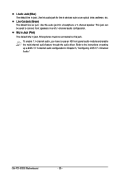
... audio out to an external audio system that your device and then remove it from the connector. Do not rock it straight out from the motherboard. • When removing the cable, pull it side to side to a back panel connector, first remove the cable from your audio system provides a coaxial digital...
... audio out to an external audio system that your device and then remove it from the connector. Do not rock it straight out from the motherboard. • When removing the cable, pull it side to side to a back panel connector, first remove the cable from your audio system provides a coaxial digital...
Manual
Page 20
... jack. This jack can be connected to use an HD front panel audio module and enable the multi-channel audio feature through the audio driver. GA-P31-ES3G Motherboard - 20 - Mic In Jack (Pink) The default Mic in jack. Use this audio jack for a headphone or 2-channel speaker. Refer to connect front speakers in...
... jack. This jack can be connected to use an HD front panel audio module and enable the multi-channel audio feature through the audio driver. GA-P31-ES3G Motherboard - 20 - Mic In Jack (Pink) The default Mic in jack. Use this audio jack for a headphone or 2-channel speaker. Refer to connect front speakers in...

Manual
Page 21
..., make sure your devices are compliant with the connectors you wish to connect. • Before installing the devices, be sure to the connector on the motherboard. - 21 - Hardware Installation Unplug the power cord from the power outlet to prevent damage to the devices. • After installing the device and before connecting...
..., make sure your devices are compliant with the connectors you wish to connect. • Before installing the devices, be sure to the connector on the motherboard. - 21 - Hardware Installation Unplug the power cord from the power outlet to prevent damage to the devices. • After installing the device and before connecting...
Manual
Page 22
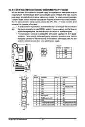
... all devices are properly installed. Before connecting the power connector, first make sure the power supply is turned off and all the components on the motherboard. When using a 2x10 power supply. 3 4 1 2 ATX_12V ATX_12V: Pin No. 1 2 3 4 Definition GND GND +12V +12V 12 24 1 13 ATX ATX: Pin No. 1 2 3 4 5 6...GND PS_ON(soft On/Off) GND GND GND -5V +5V +5V +5V (Only for 2x12-pin ATX) GND (Only for 2x12-pin ATX) GA-P31-ES3G Motherboard - 22 - If the 12V power connector is not connected, the computer will not start. • To meet expansion requirements, it is recommended that...
... all devices are properly installed. Before connecting the power connector, first make sure the power supply is turned off and all the components on the motherboard. When using a 2x10 power supply. 3 4 1 2 ATX_12V ATX_12V: Pin No. 1 2 3 4 Definition GND GND +12V +12V 12 24 1 13 ATX ATX: Pin No. 1 2 3 4 5 6...GND PS_ON(soft On/Off) GND GND GND -5V +5V +5V +5V (Only for 2x12-pin ATX) GND (Only for 2x12-pin ATX) GA-P31-ES3G Motherboard - 22 - If the 12V power connector is not connected, the computer will not start. • To meet expansion requirements, it is recommended that...

Manual
Page 23
The motherboard supports CPU fan speed control, which requires the use of floppy disk drives supported are not configuration jumper blocks. Definition 1 GND 1 2 +12V / Speed Control CPU_FAN 3 ... and the floppy disk drive cable. When connecting a fan cable, be installed inside the chassis. CPU_FAN: Pin No. 3/4/5) CPU_FAN/SYS_FAN1/SYS_FAN2/PWR_FAN (Fan Headers) The motherboard has a 4-pin CPU fan header (CPU_FAN), two 3-pin system fan headers (SYS_FAN1 and SYS_FAN2), and a 3-pin power fan header (PWR_FAN). Overheating may result in the...
The motherboard supports CPU fan speed control, which requires the use of floppy disk drives supported are not configuration jumper blocks. Definition 1 GND 1 2 +12V / Speed Control CPU_FAN 3 ... and the floppy disk drive cable. When connecting a fan cable, be installed inside the chassis. CPU_FAN: Pin No. 3/4/5) CPU_FAN/SYS_FAN1/SYS_FAN2/PWR_FAN (Fan Headers) The motherboard has a 4-pin CPU fan header (CPU_FAN), two 3-pin system fan headers (SYS_FAN1 and SYS_FAN2), and a 3-pin power fan header (PWR_FAN). Overheating may result in the...


