Manual
Page 4
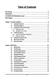
Table of Contents Box Contents ...6 OptionalItems ...6 GA-MA790X-DS4 Motherboard Layout 7 Block Diagram ...8 Chapter 1 Hardware Installation 9 1-1 Installation Precautions 9 1-2 Product Specifications 10 1-3 Installing the CPU and CPU Cooler 13 1-3-1 Installing the CPU 13 1-3-2 Installing the CPU Cooler 15 1-4 Installing the Memory 16 1-4-1 Dual Channel Memory Configuration 16 1-4-2 Installing a Memory 17 1-5 Installing an Expansion Card 18 1-6 Back Panel Connectors...
Table of Contents Box Contents ...6 OptionalItems ...6 GA-MA790X-DS4 Motherboard Layout 7 Block Diagram ...8 Chapter 1 Hardware Installation 9 1-1 Installation Precautions 9 1-2 Product Specifications 10 1-3 Installing the CPU and CPU Cooler 13 1-3-1 Installing the CPU 13 1-3-2 Installing the CPU Cooler 15 1-4 Installing the Memory 16 1-4-1 Dual Channel Memory Configuration 16 1-4-2 Installing a Memory 17 1-5 Installing an Expansion Card 18 1-6 Back Panel Connectors...

Manual
Page 8
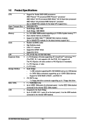
Block Diagram 1 PCIe x16 2 PCIe x8 PCIe CLK (100 MHz) or AMD Socket AM2 CPU CPU CLK+/-(200 MHz) DDR2 1066/800/667 MHz DIMM Dual Channel Memory Hyper Transport 3.0 Switch PCI Express x 16 Bus PCI Express Bus x1 x1 x1 x1 PCIe CLK (100 MHz) RTL8111B 3 PCI Express x1 RJ45 LAN PCI Bus TSB43AB23 AMD 790X AMD SB600 Dual BIOS 4 SATA 3Gb/s ATA-133/100/66/33 IDE Channel 10 USB Ports CODEC LPC BUS IT8718 Floppy LPT Port COM Port 3 IEEE 1394a PS/2 KB/Mouse Surround Speaker Out Center/Subwoofer Speaker Out Side Speaker Out MIC Line-Out Line-In SPDIF In SPDIF Out 2 PCI - 8 -
Block Diagram 1 PCIe x16 2 PCIe x8 PCIe CLK (100 MHz) or AMD Socket AM2 CPU CPU CLK+/-(200 MHz) DDR2 1066/800/667 MHz DIMM Dual Channel Memory Hyper Transport 3.0 Switch PCI Express x 16 Bus PCI Express Bus x1 x1 x1 x1 PCIe CLK (100 MHz) RTL8111B 3 PCI Express x1 RJ45 LAN PCI Bus TSB43AB23 AMD 790X AMD SB600 Dual BIOS 4 SATA 3Gb/s ATA-133/100/66/33 IDE Channel 10 USB Ports CODEC LPC BUS IT8718 Floppy LPT Port COM Port 3 IEEE 1394a PS/2 KB/Mouse Surround Speaker Out Center/Subwoofer Speaker Out Side Speaker Out MIC Line-Out Line-In SPDIF In SPDIF Out 2 PCI - 8 -

Manual
Page 9
... components. • When connecting hardware components to the internal connectors on the computer power during the installation process can become damaged as a motherboard, CPU or memory. Hardware Installation Prior to installation, carefully read the user's manual and follow these procedures: • Prior to installation, do not allow screws to come in...
... components. • When connecting hardware components to the internal connectors on the computer power during the installation process can become damaged as a motherboard, CPU or memory. Hardware Installation Prior to installation, carefully read the user's manual and follow these procedures: • Prior to installation, do not allow screws to come in...
Manual
Page 10
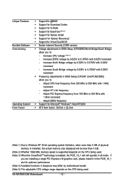
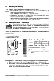
...FX processor/AMD AthlonTM 64 X2 Dual-Core processor/ AMD AthlonTM 64 processor/AMD SempronTM processor (Go to GIGABYTE's website for the latest CPU support list.) 5200/2000 MT/s North Bridge: AMD 790X South Bridge: AMD...DIMM sockets supporting up to 16 GB of system memory (Note 1) Dual channel memory architecture Support for DDR2 1066 (Note 2)/800/667 MHz memory modules (Go to GIGABYTE's website for the latest memory support list.) Realtek ALC889A codec High Definition Audio... devices - 4 x SATA 3Gb/s connectors supporting up to the internal USB headers) GA-MA790X-DS4 Motherboard - 10 -
...FX processor/AMD AthlonTM 64 X2 Dual-Core processor/ AMD AthlonTM 64 processor/AMD SempronTM processor (Go to GIGABYTE's website for the latest CPU support list.) 5200/2000 MT/s North Bridge: AMD 790X South Bridge: AMD...DIMM sockets supporting up to 16 GB of system memory (Note 1) Dual channel memory architecture Support for DDR2 1066 (Note 2)/800/667 MHz memory modules (Go to GIGABYTE's website for the latest memory support list.) Realtek ALC889A codec High Definition Audio... devices - 4 x SATA 3Gb/s connectors supporting up to the internal USB headers) GA-MA790X-DS4 Motherboard - 10 -
Manual
Page 12
... - Increase South Bridge voltage by 0.025V to 0.3750V with 0.025V increment - Adjust HT Link frequency - Increase CPU voltage (Note 5) - GA-MA790X-DS4 Motherboard - 12 - Unique Features Bundled Software Overclocking Operating System Form Factor Š Support for @BIOS Š Support for Download Center Š...Note 3) When the CrossFireXTM technology is enabled, the PCIE_16_1 slot will be less than 4 GB. (Note 2) Whether 1066 MHz memory speed is supported depends on the CPU being used . Adjust DDR2 frequency Š Support for Microsoft® Windows® Vista/XP...
... - Increase South Bridge voltage by 0.025V to 0.3750V with 0.025V increment - Adjust HT Link frequency - Increase CPU voltage (Note 5) - GA-MA790X-DS4 Motherboard - 12 - Unique Features Bundled Software Overclocking Operating System Form Factor Š Support for @BIOS Š Support for Download Center Š...Note 3) When the CrossFireXTM technology is enabled, the PCIE_16_1 slot will be less than 4 GB. (Note 2) Whether 1066 MHz memory speed is supported depends on the CPU being used . Adjust DDR2 frequency Š Support for Microsoft® Windows® Vista/XP...

Manual
Page 13
... the CPU socket and the CPU. Hardware Installation mended that the motherboard supports the CPU. (Go to your hardware specifications including the CPU, graphics card, memory, hard drive, etc. 1-3-1 Installing the CPU A. It is not installed, otherwise overheating and damage of the Socket AM2 CPU Socket A Small Triangle Marking Denotes CPU... and unplug the power cord from the power outlet before you wish to set the frequency beyond the standard specifications, please do so according to GIGABYTE's website for the peripherals.
... the CPU socket and the CPU. Hardware Installation mended that the motherboard supports the CPU. (Go to your hardware specifications including the CPU, graphics card, memory, hard drive, etc. 1-3-1 Installing the CPU A. It is not installed, otherwise overheating and damage of the Socket AM2 CPU Socket A Small Triangle Marking Denotes CPU... and unplug the power cord from the power outlet before you wish to set the frequency beyond the standard specifications, please do so according to GIGABYTE's website for the peripherals.
Manual
Page 16
... This motherboard provides four DDR2 memory sockets and supports Dual Channel Technology. GA-MA790X-DS4 Motherboard - 16 - 1-4 Installing the Memory Read the following guidelines before you begin to install the memory: • Make sure that memory of the same capacity, brand, speed, and chips be used . (Go to GIGABYTE's website for optimum performance. A memory module can be installed in...
... This motherboard provides four DDR2 memory sockets and supports Dual Channel Technology. GA-MA790X-DS4 Motherboard - 16 - 1-4 Installing the Memory Read the following guidelines before you begin to install the memory: • Make sure that memory of the same capacity, brand, speed, and chips be used . (Go to GIGABYTE's website for optimum performance. A memory module can be installed in...
Manual
Page 17
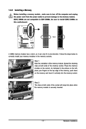
...As indicated in the picture on the left, place your memory modules in one direction. Step 2: The clips at both ends of the memory, push down on the memory and insert it can only fit in the memory sockets. Follow the steps below to correctly install your ... clips at both ends of the memory module. Hardware Installation Notch DDR2 DIMM A DDR2 memory module has a notch, so it vertically into place when the memory module is securely inserted. - 17 - Place the memory module on the socket. 1-4-2 Installing a Memory Before installing a memory module , make sure to turn off...
...As indicated in the picture on the left, place your memory modules in one direction. Step 2: The clips at both ends of the memory, push down on the memory and insert it can only fit in the memory sockets. Follow the steps below to correctly install your ... clips at both ends of the memory module. Hardware Installation Notch DDR2 DIMM A DDR2 memory module has a notch, so it vertically into place when the memory module is securely inserted. - 17 - Place the memory module on the socket. 1-4-2 Installing a Memory Before installing a memory module , make sure to turn off...

Manual
Page 38
... name (to erase the default profile name, use this task.) GA-MA790X-DS4 Motherboard - 38 - It allows you to save the current BIOS settings to a profile. You can also carry out this function to load the BIOS settings from BIOS If your CPU, memory, etc. „ Load Fail-Safe Defaults Fail-Safe defaults are...
... name (to erase the default profile name, use this task.) GA-MA790X-DS4 Motherboard - 38 - It allows you to save the current BIOS settings to a profile. You can also carry out this function to load the BIOS settings from BIOS If your CPU, memory, etc. „ Load Fail-Safe Defaults Fail-Safe defaults are...

Manual
Page 39
... ` IDE Channel 3 Master ` IDE Channel 3 Slave [None] [None] [None] [None] [None] [None] Drive A Floppy 3 Mode Support [1.44M, 3.5"] [Disabled] Halt On [All, But Keyboard] Base Memory Extended Memory 640K 239M KLJI: Move Enter: Select F5: Previous Values +/-/PU/PD: Value F10: Save F6: Fail-Safe Default ESC: Exit F1: General Help F7: Optimized...
... ` IDE Channel 3 Master ` IDE Channel 3 Slave [None] [None] [None] [None] [None] [None] Drive A Floppy 3 Mode Support [1.44M, 3.5"] [Disabled] Halt On [All, But Keyboard] Base Memory Extended Memory 640K 239M KLJI: Move Enter: Select F5: Previous Values +/-/PU/PD: Value F10: Save F6: Fail-Safe Default ESC: Exit F1: General Help F7: Optimized...

Manual
Page 40
... Typically, 640 KB will not stop for the MS-DOS operating system. GA-MA790X-DS4 Motherboard - 40 - Cylinder Number of extended memory. Drive A Allows you to None. Halt on the hard drive. Extended Memory The amount of cylinders. All, But Keyboard The system boot will not ... boot will stop . Options are determined by the BIOS POST. Head Number of floppy disk drive installed in your hard drive specifications. Memory These fields are read-only and are : Disabled (default), Drive A. The following fields display your system. Options are: None, 360K...
... Typically, 640 KB will not stop for the MS-DOS operating system. GA-MA790X-DS4 Motherboard - 40 - Cylinder Number of extended memory. Drive A Allows you to None. Halt on the hard drive. Extended Memory The amount of cylinders. All, But Keyboard The system boot will not ... boot will stop . Options are determined by the BIOS POST. Head Number of floppy disk drive installed in your hard drive specifications. Memory These fields are read-only and are : Disabled (default), Drive A. The following fields display your system. Options are: None, 360K...

Manual
Page 47
... this function, you need an ATX power supply providing at least 1A on by a PS/2 mouse wake-up to 5 characters and then press to accept. Memory The system returns to Password. When prompted for Windows® Vista® operating system. (Default: Enabled) Power On By Mouse Allows the system to be...
... this function, you need an ATX power supply providing at least 1A on by a PS/2 mouse wake-up to 5 characters and then press to accept. Memory The system returns to Password. When prompted for Windows® Vista® operating system. (Default: Enabled) Power On By Mouse Allows the system to be...
Manual
Page 51
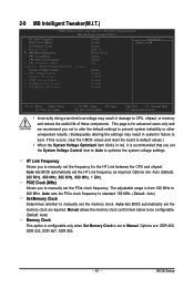
... prevent system instability or other unexpected results. (Inadequately altering the settings may result in damage to CPU, chipset, or memory and reduce the useful life of these components. 2-9 MB Intelligent Tweaker(M.I.T.) CMOS Setup Utility-Copyright (C) 1984-2007 Award ...Software MB Intelligent Tweaker(M.I.T.) HT Link Frequency PCIE Clock (MHz) Set Memory Clock x Memory Clock ` DRAM Configuration CPU Clock Ratio CPU Host Clock Control x CPU Frequency (MHz) ******** System Voltage Optimized System Voltage Control ...
... prevent system instability or other unexpected results. (Inadequately altering the settings may result in damage to CPU, chipset, or memory and reduce the useful life of these components. 2-9 MB Intelligent Tweaker(M.I.T.) CMOS Setup Utility-Copyright (C) 1984-2007 Award ...Software MB Intelligent Tweaker(M.I.T.) HT Link Frequency PCIE Clock (MHz) Set Memory Clock x Memory Clock ` DRAM Configuration CPU Clock Ratio CPU Host Clock Control x CPU Frequency (MHz) ******** System Voltage Optimized System Voltage Control ...

Manual
Page 53
...0.375V at 0.025V increment. System Voltage Control Determines whether to set North Bridge voltage. The adjustable range is from 200 MHz to set memory voltage. Important It is dependent on the CPU being used. Auto lets BIOS automatically set in damage to set South Bridge voltage. NorthBridge Volt... for 20 seconds to allow for the installed CPU. Normal Supplies the North Bridge voltage as required. (Default) +0.025V ~ +0.375V Increases memory voltage by 0.025V to be set the system voltages as required. Normal sets the CPU voltage as required. Normal Supplies the...
...0.375V at 0.025V increment. System Voltage Control Determines whether to set North Bridge voltage. The adjustable range is from 200 MHz to set memory voltage. Important It is dependent on the CPU being used. Auto lets BIOS automatically set in damage to set South Bridge voltage. NorthBridge Volt... for 20 seconds to allow for the installed CPU. Normal Supplies the North Bridge voltage as required. (Default) +0.025V ~ +0.375V Increases memory voltage by 0.025V to be set the system voltages as required. Normal sets the CPU voltage as required. Normal Supplies the...

Manual
Page 61
actual size requirements vary, depending on the amount of data). • It is recommended to back up your system data and perform restoration of system memory • VESA compatible graphics card • Windows® 2000 with Xpress Recovery cannot be restored using Xpress Recovery2. • USB hard drives are not supported. &#...
actual size requirements vary, depending on the amount of data). • It is recommended to back up your system data and perform restoration of system memory • VESA compatible graphics card • Windows® 2000 with Xpress Recovery cannot be restored using Xpress Recovery2. • USB hard drives are not supported. &#...

Manual
Page 71
...button Toggles among Easy Mode, Advanced Mode, and Graphics Mode Displays the CPU frequency Shows the supported function(s) Go to GIGABYTE website to update EasyTune 5 Pro Opens EasyTune 5 Pro help file Quits or minimizes the EasyTune 5 Pro interface Performance Enhancement... components. SMART FAN 4. Live Update 10. Turbo Boost Description Enters the OVERCLOCKING setting page Enters the C.I .B. may provide optimizations for CPU and memory, enhancing the performance of these components. - 71 - EASY MODE/ADVANCED MODE/ GRAPHICS 7. Display Area 8. and M.I .A. OVERCLOCKING 2. GO 6....
...button Toggles among Easy Mode, Advanced Mode, and Graphics Mode Displays the CPU frequency Shows the supported function(s) Go to GIGABYTE website to update EasyTune 5 Pro Opens EasyTune 5 Pro help file Quits or minimizes the EasyTune 5 Pro interface Performance Enhancement... components. SMART FAN 4. Live Update 10. Turbo Boost Description Enters the OVERCLOCKING setting page Enters the C.I .B. may provide optimizations for CPU and memory, enhancing the performance of these components. - 71 - EASY MODE/ADVANCED MODE/ GRAPHICS 7. Display Area 8. and M.I .A. OVERCLOCKING 2. GO 6....

Manual
Page 72
.... Follow the steps below to enable the ReadyBoost function: Step 1: Go to three times the amount of memory to use for ReadyBoost using the slider or spin box. GA-MA790X-DS4 Motherboard - 72 - Step 2: In the ReadyBoost tab, select Use this device. 4-4 Windows Vista ReadyBoost ...Windows ReadyBoost allows you to use flash memory on a Windows Vista certified USB flash drive to use for ReadyBoost acceleration...
.... Follow the steps below to enable the ReadyBoost function: Step 1: Go to three times the amount of memory to use for ReadyBoost using the slider or spin box. GA-MA790X-DS4 Motherboard - 72 - Step 2: In the ReadyBoost tab, select Use this device. 4-4 Windows Vista ReadyBoost ...Windows ReadyBoost allows you to use flash memory on a Windows Vista certified USB flash drive to use for ReadyBoost acceleration...

Manual
Page 75
... not want to enter the Controller Configuration window. To delete an array, press to enter the View Drive Assignments window. Appendix Step 1: After the POST memory test begins and before the operating system boot begins, look for a message which says "Press to enter the Define LD window. To create an array...
... not want to enter the Controller Configuration window. To delete an array, press to enter the View Drive Assignments window. Appendix Step 1: After the POST memory test begins and before the operating system boot begins, look for a message which says "Press to enter the Define LD window. To create an array...
Manual
Page 92
...terminals of standby power after the computer shuts down ? In the Main Menu, press + to the Support\Motherboard\FAQ page on GIGABYTE's website. A: If your speaker is the light of my keyboard/optical mouse still on the CLR_CMOS jumper in the BIOS Setup ...: CMOS setting error 1 long, 1 short: Memory or motherboard error 1 long, 2 short: Monitor or graphics card error 1 long, 3 short: Keyboard error 1 long, 9 short: BIOS ROM error Continuous long beeps: Graphics card not inserted properly Continuous short beeps: Power error GA-MA790X-DS4 Motherboard - 92 - Press to the instructions on...
...terminals of standby power after the computer shuts down ? In the Main Menu, press + to the Support\Motherboard\FAQ page on GIGABYTE's website. A: If your speaker is the light of my keyboard/optical mouse still on the CLR_CMOS jumper in the BIOS Setup ...: CMOS setting error 1 long, 1 short: Memory or motherboard error 1 long, 2 short: Monitor or graphics card error 1 long, 3 short: Keyboard error 1 long, 9 short: BIOS ROM error Continuous long beeps: Graphics card not inserted properly Continuous short beeps: Power error GA-MA790X-DS4 Motherboard - 92 - Press to the instructions on...

Manual
Page 93
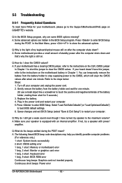
START Turn off the power. No Check if the CPU cooler is installed properly on the memory slot. Yes Check if the memory is attached to the CPU securely. Yes Isolate the short circuit. The problem is verified and solved. Connect the CPU cooler power cable to... of the CPU cooler connected to enter BIOS Setup. Connect the ATX main power cable and the 12V power cable. No Correctly insert the memory into the memory socket. Remove all peripherals, connecting cables, and power cord etc. Press to the CPU_FAN header properly? A (Continued...) - 93 - Select "Save & Exit Setup" ...
START Turn off the power. No Check if the CPU cooler is installed properly on the memory slot. Yes Check if the memory is attached to the CPU securely. Yes Isolate the short circuit. The problem is verified and solved. Connect the CPU cooler power cable to... of the CPU cooler connected to enter BIOS Setup. Connect the ATX main power cable and the 12V power cable. No Correctly insert the memory into the memory socket. Remove all peripherals, connecting cables, and power cord etc. Press to the CPU_FAN header properly? A (Continued...) - 93 - Select "Save & Exit Setup" ...


