Manual
Page 4
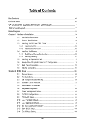
Table of Contents Box Contents...6 Optional Items...6 GA-MA785GPMT-UD2H/GA-MA785GMT-UD2H(US2H 7 Motherboard Layout...7 Block Diagram...8 Chapter 1 Hardware Installation 9 1-1 Installation Precautions 9 1-2 Product Specifications 10 1-3 Installing the CPU and CPU Cooler 13 1-3-1 Installing the CPU 13 1-3-2 Installing the CPU Cooler 15 1-4 Installing the Memory 16 1-4-1 Dual Channel Memory Configuration 16 1-4-2 Installing a Memory 17 1-5 Installing an Expansion Card 18...
Table of Contents Box Contents...6 Optional Items...6 GA-MA785GPMT-UD2H/GA-MA785GMT-UD2H(US2H 7 Motherboard Layout...7 Block Diagram...8 Chapter 1 Hardware Installation 9 1-1 Installation Precautions 9 1-2 Product Specifications 10 1-3 Installing the CPU and CPU Cooler 13 1-3-1 Installing the CPU 13 1-3-2 Installing the CPU Cooler 15 1-4 Installing the Memory 16 1-4-1 Dual Channel Memory Configuration 16 1-4-2 Installing a Memory 17 1-5 Installing an Expansion Card 18...

Manual
Page 8
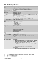
Block Diagram PCIe CLK (100 MHz) AM3 CPU CPU CLK+/- (200 MHz) DDR3 1666 (O.C.)/1333/1066 MHz 1 PCI Express x16 Dual Channel Memory Hyper Transport 3.0 PCI Express x16 PCI Express Bus x1 PCIe CLK (100 MHz) 1 PCI Express x1 RTL8111C RJ45 LAN Dual BIOS PCI Bus TSB43AB23 2 IEEE ... Speaker Out Center/Subwoofer Speaker Out Side Speaker Out MIC Line Out Line In S/PDIF In S/ PDIF Out 2 PCI PCI CLK (33 MHz) j Only for GA-MA785GPMT-UD2H. (Note) Simultaneous output for DVI-D and HDMI is not supported. - 8 -
Block Diagram PCIe CLK (100 MHz) AM3 CPU CPU CLK+/- (200 MHz) DDR3 1666 (O.C.)/1333/1066 MHz 1 PCI Express x16 Dual Channel Memory Hyper Transport 3.0 PCI Express x16 PCI Express Bus x1 PCIe CLK (100 MHz) 1 PCI Express x1 RTL8111C RJ45 LAN Dual BIOS PCI Bus TSB43AB23 2 IEEE ... Speaker Out Center/Subwoofer Speaker Out Side Speaker Out MIC Line Out Line In S/PDIF In S/ PDIF Out 2 PCI PCI CLK (33 MHz) j Only for GA-MA785GPMT-UD2H. (Note) Simultaneous output for DVI-D and HDMI is not supported. - 8 -

Manual
Page 9
... leads or connectors. • It is best to wear an electrostatic discharge (ESD) wrist strap when handling electronic com- ponents such as a motherboard, CPU or memory. These stickers are required for warranty validation. • Always remove the AC power by your hardware components are connected. • To prevent damage to the...
... leads or connectors. • It is best to wear an electrostatic discharge (ESD) wrist strap when handling electronic com- ponents such as a motherboard, CPU or memory. These stickers are required for warranty validation. • Always remove the AC power by your hardware components are connected. • To prevent damage to the...
Manual
Page 10
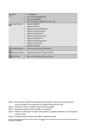
...sockets supporting up to 16 GB of system memory (Note 1) Dual channel memory architecture Support for DDR3 1666 (O.C.)/1333/1066 MHz memory modules (Go to GIGABYTE's website for the latest memory support list.) Intergrated Memory 128MB DDR3 SidePort memory Onboard Graphics Audio ... chip: - 1 x floppy disk drive connector supporting up to 1 floppy disk drive "*" j k The GA-MA785GPMT-UD2H/GA-MA785GMT-UD2H adopts All-Solid Capacitor design. Only for GA-MA785GMT-UD2H. Only for GA-MA785GPMT-UD2H.
...sockets supporting up to 16 GB of system memory (Note 1) Dual channel memory architecture Support for DDR3 1666 (O.C.)/1333/1066 MHz memory modules (Go to GIGABYTE's website for the latest memory support list.) Intergrated Memory 128MB DDR3 SidePort memory Onboard Graphics Audio ... chip: - 1 x floppy disk drive connector supporting up to 1 floppy disk drive "*" j k The GA-MA785GPMT-UD2H/GA-MA785GMT-UD2H adopts All-Solid Capacitor design. Only for GA-MA785GMT-UD2H. Only for GA-MA785GPMT-UD2H.
Manual
Page 12
... Form Factor; 24.3cm x 24.3cm (Note 1) Due to Windows Vista/XP 32-bit operating system limitation, when more than 4 GB of physical memory is installed, the actual memory size displayed will be less than 4 GB. (Note 2) The DVI-D port does not support D-Sub connection by adapter. (Note 3) Simultaneous output for DVI...
... Form Factor; 24.3cm x 24.3cm (Note 1) Due to Windows Vista/XP 32-bit operating system limitation, when more than 4 GB of physical memory is installed, the actual memory size displayed will be less than 4 GB. (Note 2) The DVI-D port does not support D-Sub connection by adapter. (Note 3) Simultaneous output for DVI...

Manual
Page 13
Locate the pin one of thermal grease on the computer if the CPU cooler is not recommended that the motherboard supports the CPU. (Go to GIGABYTE's website for the peripherals. A Small Triangle Mark Denotes Pin One of the CPU socket and the CPU. If you wish to set beyond the... standard specifications, please do so according to your hardware specifications including the CPU, graphics card, memory, hard drive, etc. 1-3-1 Installing the CPU A. Hardware Installation age of the CPU may locate the notches on both sides of the CPU and ...
Locate the pin one of thermal grease on the computer if the CPU cooler is not recommended that the motherboard supports the CPU. (Go to GIGABYTE's website for the peripherals. A Small Triangle Mark Denotes Pin One of the CPU socket and the CPU. If you wish to set beyond the... standard specifications, please do so according to your hardware specifications including the CPU, graphics card, memory, hard drive, etc. 1-3-1 Installing the CPU A. Hardware Installation age of the CPU may locate the notches on both sides of the CPU and ...
Manual
Page 16
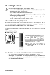
... divided into two channels and each channel has two memory sockets as following guidelines before you begin to GIGABYTE's website for optimum performance. A memory module can be used . (Go to install the memory: • Make sure that the motherboard supports the memory. It is recommended that memory of the same capacity, brand, speed, and chips be...
... divided into two channels and each channel has two memory sockets as following guidelines before you begin to GIGABYTE's website for optimum performance. A memory module can be used . (Go to install the memory: • Make sure that the motherboard supports the memory. It is recommended that memory of the same capacity, brand, speed, and chips be...
Manual
Page 17
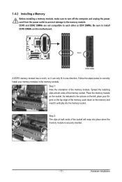
...on the top edge of the memory, push down on the memory and insert it can only fit in the memory sockets. Notch DDR3 DIMM A DDR3 memory module has a notch, so it vertically into place when the memory module is securely inserted. - 17 - Place the memory module on this motherboard. As ...indicated in the picture on the left, place your memory modules in one direction....
...on the top edge of the memory, push down on the memory and insert it can only fit in the memory sockets. Notch DDR3 DIMM A DDR3 memory module has a notch, so it vertically into place when the memory module is securely inserted. - 17 - Place the memory module on this motherboard. As ...indicated in the picture on the left, place your memory modules in one direction....
Manual
Page 21
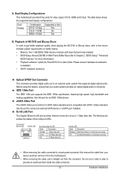
...; When removing the cable, pull it side to side to connect an external SATA device or a SATA port multiplier. A. The table below . • Memory: Two 1 GB DDR3 1066 memory modules with SATA 1.5Gb/s standard. Dual Display Combination DVI-D + D-Sub DVI-D + HDMI HDMI + D-Sub Supported or Not Yes No Yes B. IEEE 1394a Port...
...; When removing the cable, pull it side to side to connect an external SATA device or a SATA port multiplier. A. The table below . • Memory: Two 1 GB DDR3 1066 memory modules with SATA 1.5Gb/s standard. Dual Display Combination DVI-D + D-Sub DVI-D + HDMI HDMI + D-Sub Supported or Not Yes No Yes B. IEEE 1394a Port...

Manual
Page 38
You can use the SPACE key) and then press to complete. F12: Load CMOS from BIOS If your CPU, memory, etc. Standard CMOS Features Use this menu to configure the system time and date, hard drive types, floppy disk drive types, and the type ...
You can use the SPACE key) and then press to complete. F12: Load CMOS from BIOS If your CPU, memory, etc. Standard CMOS Features Use this menu to configure the system time and date, hard drive types, floppy disk drive types, and the type ...
Manual
Page 39
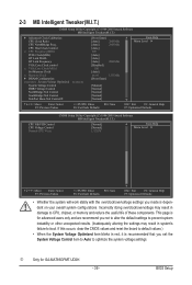
... and reset the board to default values.) • When the System Voltage Optimized item blinks in red, it is for GA-MA785GPMT-UD2H. - 39 - BIOS Setup 2-3 MB Intelligent Tweaker(M.I.T.) CMOS Setup Utility-Copyright (C) 1984-2009 Award Software MB Intelligent Tweaker(M.I...MHz) PCIE Clock(MHz) HT Link Width HT Link Frequency VGA Core Clock control x VGA Core Clock(MHz) Set Memory Clock x Memory Clock } DRAM Configuration ******** System Voltage Optimized ******** System Voltage Control DDR3 Voltage Control NorthBridge Volt Control SouthBridge Volt Control...
... and reset the board to default values.) • When the System Voltage Optimized item blinks in red, it is for GA-MA785GPMT-UD2H. - 39 - BIOS Setup 2-3 MB Intelligent Tweaker(M.I.T.) CMOS Setup Utility-Copyright (C) 1984-2009 Award Software MB Intelligent Tweaker(M.I...MHz) PCIE Clock(MHz) HT Link Width HT Link Frequency VGA Core Clock control x VGA Core Clock(MHz) Set Memory Clock x Memory Clock } DRAM Configuration ******** System Voltage Optimized ******** System Voltage Control DDR3 Voltage Control NorthBridge Volt Control SouthBridge Volt Control...

Manual
Page 41
...clock frequency. Auto sets the PCIe clock frequency to standard 100 MHz. (Default: Auto) HT Link Width Allows you to 2000 MHz. X8.00 Sets Memory Clock to automatically adjust the CPU host frequency. CPU NorthBridge Freq. Manual allows the CPU Frequency (MHz) item below to x1~x10 (200 MHz~2.0 GHz...Width to 500 MHz. This item is configurable only if the VGA Core Clock control option is set the VGA Core clock. X5.33 Sets Memory Clock to alter the North Bridge controller frequency for automated system reboot, or clear the CMOS values to reset the board to X4.00. ...
...clock frequency. Auto sets the PCIe clock frequency to standard 100 MHz. (Default: Auto) HT Link Width Allows you to 2000 MHz. X8.00 Sets Memory Clock to automatically adjust the CPU host frequency. CPU NorthBridge Freq. Manual allows the CPU Frequency (MHz) item below to x1~x10 (200 MHz~2.0 GHz...Width to 500 MHz. This item is configurable only if the VGA Core Clock control option is set the VGA Core clock. X5.33 Sets Memory Clock to alter the North Bridge controller frequency for automated system reboot, or clear the CMOS values to reset the board to X4.00. ...
Manual
Page 42
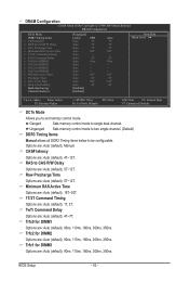
...x Row Cycle Time x RAS to RAS Delay Bank interleaving Channel interleave [Unganged] [Auto] SPD Auto 7T Auto 7T Auto 7T Auto 30T Auto -- Unganged Sets memory control mode to two single-channel. (Default) DDR3 Timing Items Manual allows all DDR3 Timing items below to set... memory control mode. DRAM Configuration CMOS Setup Utility-Copyright (C) 1984-2009 Award Software DRAM Configuration DCTs Mode DDR3 Timing Items x CAS# latency x RAS to CAS R/W Delay x...
...x Row Cycle Time x RAS to RAS Delay Bank interleaving Channel interleave [Unganged] [Auto] SPD Auto 7T Auto 7T Auto 7T Auto 30T Auto -- Unganged Sets memory control mode to two single-channel. (Default) DDR3 Timing Items Manual allows all DDR3 Timing items below to set... memory control mode. DRAM Configuration CMOS Setup Utility-Copyright (C) 1984-2009 Award Software DRAM Configuration DCTs Mode DDR3 Timing Items x CAS# latency x RAS to CAS R/W Delay x...
Manual
Page 43
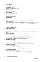
...******** System Voltage Control Determines whether to set the system voltages. Enabled allows the system to simultaneously access different channels of the memory to set the system voltages as required. Normal Supplies the North Bridge voltage as required. (Default) -0.1V ~ +0.2V ...(default), 4T~7T. Auto lets the BIOS automatically set memory voltage. Precharge Time Options are : Auto (default), 5T~8T, 10T, 12T. Note: Increasing memory voltage may result in damage to 0.750V at 0.1V increment. Trfc3 for GA-MA785GPMT-UD2H. - 43 - j Only for DIMM4 Options are: Auto...
...******** System Voltage Control Determines whether to set the system voltages. Enabled allows the system to simultaneously access different channels of the memory to set the system voltages as required. Normal Supplies the North Bridge voltage as required. (Default) -0.1V ~ +0.2V ...(default), 4T~7T. Auto lets the BIOS automatically set memory voltage. Precharge Time Options are : Auto (default), 5T~8T, 10T, 12T. Note: Increasing memory voltage may result in damage to 0.750V at 0.1V increment. Trfc3 for GA-MA785GPMT-UD2H. - 43 - j Only for DIMM4 Options are: Auto...

Manual
Page 45
... 3 Master } IDE Channel 3 Slave [None] [None] [None] [None] [None] [None] [None] [None] Drive A Floppy 3 Mode Support [1.44M, 3.5"] [Disabled] Halt On [All, But Keyboard] Base Memory Extended Memory 640K 1790M Move Enter: Select F5: Previous Values +/-/PU/PD: Value F10: Save F6: Fail-Safe Defaults ESC: Exit F1: General Help F7: Optimized Defaults...
... 3 Master } IDE Channel 3 Slave [None] [None] [None] [None] [None] [None] [None] [None] Drive A Floppy 3 Mode Support [1.44M, 3.5"] [Disabled] Halt On [All, But Keyboard] Base Memory Extended Memory 640K 1790M Move Enter: Select F5: Previous Values +/-/PU/PD: Value F10: Save F6: Fail-Safe Defaults ESC: Exit F1: General Help F7: Optimized Defaults...

Manual
Page 46
... will stop for an error during the POST. Base Memory Also called conventional memory. Precomp Write precompensation cylinder. Sector Number of heads. Options are : Disabled (default), Drive A. Cylinder Number of extended memory. Landing Zone Landing zone. Halt On Allows you to...None. Options are : None, 360K/5.25", 1.2M/5.25", 720K/3.5", 1.44M/3.5", 2.88M/3.5". Memory These fields are read-only and are determined by the BIOS POST. Extended Memory The amount of cylinders. BIOS Setup - 46 - Capacity Approximate capacity of floppy disk drive installed...
... will stop for an error during the POST. Base Memory Also called conventional memory. Precomp Write precompensation cylinder. Sector Number of heads. Options are : Disabled (default), Drive A. Cylinder Number of extended memory. Landing Zone Landing zone. Halt On Allows you to...None. Options are : None, 360K/5.25", 1.2M/5.25", 720K/3.5", 1.44M/3.5", 2.88M/3.5". Memory These fields are read-only and are determined by the BIOS POST. Extended Memory The amount of cylinders. BIOS Setup - 46 - Capacity Approximate capacity of floppy disk drive installed...
Manual
Page 47
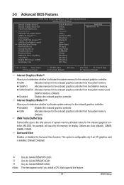
... S.M.A.R.T. Disabled Disables the onboard graphics controller. Surround View Enables or disables the Surround View function. BIOS Setup UMA Allocates memory for GA-MA785GPMT-UD2H. SidePort Allocates memory for the onboard graphics controller from the SidePort memory. UMA+SidePort Allocates memory for the onboard graphics controller from the system memory and SidePort memory. (Default) Disabled Disables the onboard graphics controller.
... S.M.A.R.T. Disabled Disables the onboard graphics controller. Surround View Enables or disables the Surround View function. BIOS Setup UMA Allocates memory for GA-MA785GPMT-UD2H. SidePort Allocates memory for the onboard graphics controller from the SidePort memory. UMA+SidePort Allocates memory for the onboard graphics controller from the system memory and SidePort memory. (Default) Disabled Disables the onboard graphics controller.
Manual
Page 54
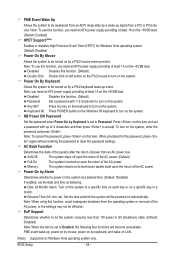
..., power on the system. Resume Time (hh: mm: ss): Set the time at a desired time. (Default: Disabled) If enabled, set to Password. BIOS Setup - 54 - Memory The system returns to its last known awake state upon the return of power from an AC power loss. KB Power ON Password Set the...
..., power on the system. Resume Time (hh: mm: ss): Set the time at a desired time. (Default: Disabled) If enabled, set to Password. BIOS Setup - 54 - Memory The system returns to its last known awake state upon the return of power from an AC power loss. KB Power ON Password Set the...

Manual
Page 65
.... • As Xpress Recovery2 will check the first physical hard drive (Note) for the operating system. System Requirements: • At least 512 MB of system memory • VESA compatible graphics card • Windows XP with Xpress Recovery cannot be restored using Xpress Recovery2. • USB hard drives are not supported. •...
.... • As Xpress Recovery2 will check the first physical hard drive (Note) for the operating system. System Requirements: • At least 512 MB of system memory • VESA compatible graphics card • Windows XP with Xpress Recovery cannot be restored using Xpress Recovery2. • USB hard drives are not supported. •...

Manual
Page 72
... monitor hardware temperature, voltage and fan speed and set . Incorrectly doing overclock/overvoltage may result in EasyTune 6 may occur. 4-3 EasyTune 6 GIGABYTE's EasyTune 6 is a simple and easy-to-use interface that allows users to fine-tune their system-related information without the need to specify...C.I.A.2 level and a Smart Fan mode. The EasyTune 6 Interface Tabs Information Tab Function The CPU tab provides information on the installed memory module(s). Grayed-out area(s) indicates that you to adjust the CPU FSB only. • Advanced mode allows you fully know each...
... monitor hardware temperature, voltage and fan speed and set . Incorrectly doing overclock/overvoltage may result in EasyTune 6 may occur. 4-3 EasyTune 6 GIGABYTE's EasyTune 6 is a simple and easy-to-use interface that allows users to fine-tune their system-related information without the need to specify...C.I.A.2 level and a Smart Fan mode. The EasyTune 6 Interface Tabs Information Tab Function The CPU tab provides information on the installed memory module(s). Grayed-out area(s) indicates that you to adjust the CPU FSB only. • Advanced mode allows you fully know each...


