Manual
Page 4
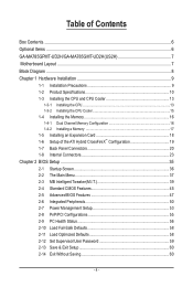
Table of Contents Box Contents...6 Optional Items...6 GA-MA785GPMT-UD2H/GA-MA785GMT-UD2H(US2H 7 Motherboard Layout...7 Block Diagram...8 Chapter 1 Hardware Installation 9 1-1 Installation Precautions 9 1-2 Product Specifications 10 1-3 Installing the CPU and CPU Cooler 13 1-3-1 Installing the CPU 13 1-3-2 Installing the CPU Cooler 15 1-4 Installing the Memory 16 1-4-1 Dual Channel Memory Configuration 16 1-4-2 Installing a Memory 17 1-5 Installing an Expansion Card 18 1-6 Setup...
Table of Contents Box Contents...6 Optional Items...6 GA-MA785GPMT-UD2H/GA-MA785GMT-UD2H(US2H 7 Motherboard Layout...7 Block Diagram...8 Chapter 1 Hardware Installation 9 1-1 Installation Precautions 9 1-2 Product Specifications 10 1-3 Installing the CPU and CPU Cooler 13 1-3-1 Installing the CPU 13 1-3-2 Installing the CPU Cooler 15 1-4 Installing the Memory 16 1-4-1 Dual Channel Memory Configuration 16 1-4-2 Installing a Memory 17 1-5 Installing an Expansion Card 18 1-6 Setup...

Manual
Page 8
Block Diagram PCIe CLK (100 MHz) AM3 CPU CPU CLK+/- (200 MHz) DDR3 1666 (O.C.)/1333/1066 MHz 1 PCI Express x16 Dual Channel Memory Hyper Transport 3.0 PCI Express x16 PCI Express Bus x1 PCIe CLK (... Speaker Out Center/Subwoofer Speaker Out Side Speaker Out MIC Line Out Line In S/PDIF In S/ PDIF Out 2 PCI PCI CLK (33 MHz) j Only for GA-MA785GPMT-UD2H. (Note) Simultaneous output for DVI-D and HDMI is not supported. - 8 -
Block Diagram PCIe CLK (100 MHz) AM3 CPU CPU CLK+/- (200 MHz) DDR3 1666 (O.C.)/1333/1066 MHz 1 PCI Express x16 Dual Channel Memory Hyper Transport 3.0 PCI Express x16 PCI Express Bus x1 PCIe CLK (... Speaker Out Center/Subwoofer Speaker Out Side Speaker Out MIC Line Out Line In S/PDIF In S/ PDIF Out 2 PCI PCI CLK (33 MHz) j Only for GA-MA785GPMT-UD2H. (Note) Simultaneous output for DVI-D and HDMI is not supported. - 8 -

Manual
Page 9
... other hardware components. • When connecting hardware components to the internal connectors on the computer power during the installation process can become damaged as a motherboard, CPU or memory. Prior to installation, carefully read the user's manual and follow these procedures: • Prior to installation, do not remove or break motherboard S/N (Serial...
... other hardware components. • When connecting hardware components to the internal connectors on the computer power during the installation process can become damaged as a motherboard, CPU or memory. Prior to installation, carefully read the user's manual and follow these procedures: • Prior to installation, do not remove or break motherboard S/N (Serial...
Manual
Page 10
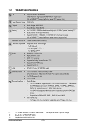
Only for GA-MA785GPMT-UD2H. Hardware Installation - 10 - Only for GA-MA785GMT-UD2H. 1-2 Product Specifications CPU Support for AM3 processors: AMD Phenom™ II processor/ AMD Athlon™ II processor (Go to GIGABYTE's website for the latest CPU support list.) Hyper Transport Bus... iTE IT8718 chip: - 1 x floppy disk drive connector supporting up to 1 floppy disk drive "*" j k The GA-MA785GPMT-UD2H/GA-MA785GMT-UD2H adopts All-Solid Capacitor design. Support for CD In LAN RTL8111C chip (10/100/1000 Mbit) Expansion Slots ...
Only for GA-MA785GPMT-UD2H. Hardware Installation - 10 - Only for GA-MA785GMT-UD2H. 1-2 Product Specifications CPU Support for AM3 processors: AMD Phenom™ II processor/ AMD Athlon™ II processor (Go to GIGABYTE's website for the latest CPU support list.) Hyper Transport Bus... iTE IT8718 chip: - 1 x floppy disk drive connector supporting up to 1 floppy disk drive "*" j k The GA-MA785GPMT-UD2H/GA-MA785GMT-UD2H adopts All-Solid Capacitor design. Support for CD In LAN RTL8111C chip (10/100/1000 Mbit) Expansion Slots ...

Manual
Page 11
... 1 x 8-pin ATX 12V power connector 1 x floppy disk drive connector 1 x IDE connector 5 x SATA 3Gb/s connectors 1 x CPU fan header 1 x system fan header 1 x North Bridge fan header 1 x front panel header 1 x front panel audio header 1 ... In/Line Out/Microphone) iTE IT8718 chip Hardware Monitor w w w w w w System voltage detection CPU/System temperature detection CPU/System fan speed detection CPU overheating warning CPU/System/Power fan fail warning CPU/System fan speed control (Note 4) - 11 - USB IEEE 1394 Internal w Connectors w w w ...
... 1 x 8-pin ATX 12V power connector 1 x floppy disk drive connector 1 x IDE connector 5 x SATA 3Gb/s connectors 1 x CPU fan header 1 x system fan header 1 x North Bridge fan header 1 x front panel header 1 x front panel audio header 1 ... In/Line Out/Microphone) iTE IT8718 chip Hardware Monitor w w w w w w System voltage detection CPU/System temperature detection CPU/System fan speed detection CPU overheating warning CPU/System/Power fan fail warning CPU/System fan speed control (Note 4) - 11 - USB IEEE 1394 Internal w Connectors w w w ...
Manual
Page 12
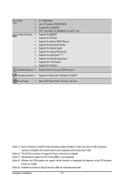
... 4 GB. (Note 2) The DVI-D port does not support D-Sub connection by adapter. (Note 3) Simultaneous output for DVI-D and HDMI is not supported. (Note 4) Whether the CPU/system fan speed control function is supported will depend on the CPU/system cooler you install. (Note 5) Available functions in EasyTune may differ by motherboard model.
... 4 GB. (Note 2) The DVI-D port does not support D-Sub connection by adapter. (Note 3) Simultaneous output for DVI-D and HDMI is not supported. (Note 4) Whether the CPU/system fan speed control function is supported will depend on the CPU/system cooler you install. (Note 5) Available functions in EasyTune may differ by motherboard model.

Manual
Page 13
... Mark Denotes Pin One of the CPU socket and the CPU. Hardware Installation Locate the pin one of the CPU. 1-3 Installing the CPU and CPU Cooler Read the following guidelines before you begin to install the CPU: • Make sure that the motherboard supports the CPU. (Go to GIGABYTE's website for the latest CPU support list.) • Always turn...
... Mark Denotes Pin One of the CPU socket and the CPU. Hardware Installation Locate the pin one of the CPU. 1-3 Installing the CPU and CPU Cooler Read the following guidelines before you begin to install the CPU: • Make sure that the motherboard supports the CPU. (Go to GIGABYTE's website for the latest CPU support list.) • Always turn...

Manual
Page 14
... lever and latching it into the socket. The CPU cannot fit in if oriented incorrectly. Hardware Installation - 14 - CPU Socket Locking Lever Step 1: Completely lift up the CPU socket locking lever. Step 2: Align the CPU pin one finger down on the CPU socket and gently insert the CPU into the fully locked position. Make sure that...
... lever and latching it into the socket. The CPU cannot fit in if oriented incorrectly. Hardware Installation - 14 - CPU Socket Locking Lever Step 1: Completely lift up the CPU socket locking lever. Step 2: Align the CPU pin one finger down on the CPU socket and gently insert the CPU into the fully locked position. Make sure that...

Manual
Page 15
... the example.) Step 1: Apply an even and thin layer of thermal grease on the surface of the installed CPU. 1-3-2 Installing the CPU Cooler Follow the steps below to correctly install the CPU cooler on the CPU. (The following procedure uses the GIGABYTE cooler as the picture above shows) to lock into place. (Refer to your...
... the example.) Step 1: Apply an even and thin layer of thermal grease on the surface of the installed CPU. 1-3-2 Installing the CPU Cooler Follow the steps below to correctly install the CPU cooler on the CPU. (The following procedure uses the GIGABYTE cooler as the picture above shows) to lock into place. (Refer to your...
Manual
Page 16
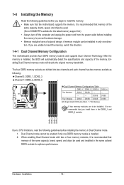
... mode will automatically detect the specifications and capacity of the same capacity, brand, speed, and chips be used . (Go to GIGABYTE's website for optimum performance. DDR3_1 DDR3_2 DDR3_3 DDR3_4 Due to CPU limitations, read the following guidelines before installing the memory to install the memory: • Make sure that you begin to...
... mode will automatically detect the specifications and capacity of the same capacity, brand, speed, and chips be used . (Go to GIGABYTE's website for optimum performance. DDR3_1 DDR3_2 DDR3_3 DDR3_4 Due to CPU limitations, read the following guidelines before installing the memory to install the memory: • Make sure that you begin to...

Manual
Page 24
... -5V +5V +5V +5V (Only for 2x12-pin ATX) GND (Only for 2x12-pin ATX) Hardware Installation - 24 - Connect the power supply cable to the CPU. 1/2) ATX_12V_2X4/ATX (2x4 12V Power Connector and 2x12 Main Power Connector) With the use of the power connector, the power supply can supply enough stable...
... -5V +5V +5V +5V (Only for 2x12-pin ATX) GND (Only for 2x12-pin ATX) Hardware Installation - 24 - Connect the power supply cable to the CPU. 1/2) ATX_12V_2X4/ATX (2x4 12V Power Connector and 2x12 Main Power Connector) With the use of the power connector, the power supply can supply enough stable...

Manual
Page 25
... No. 1 2 3 4 Definition GND +12V / Speed Control Sense Reserve 5) NB_FAN (North Bridge Fan Header) Connect the North Bridge fan cable to prevent your CPU, North Bridge and system from overheating. A red power connector wire indicates a positive connection and requires a +12V voltage. Pin No. Definition 1 GND 1 2 +... Each fan header supplies a +12V power voltage and possesses a foolproof insertion design. Overheating may result in damage to the CPU/North Bridge or the system may hang. • These fan headers are designed with color-coded power connector wires. The black...
... No. 1 2 3 4 Definition GND +12V / Speed Control Sense Reserve 5) NB_FAN (North Bridge Fan Header) Connect the North Bridge fan cable to prevent your CPU, North Bridge and system from overheating. A red power connector wire indicates a positive connection and requires a +12V voltage. Pin No. Definition 1 GND 1 2 +... Each fan header supplies a +12V power voltage and possesses a foolproof insertion design. Overheating may result in damage to the CPU/North Bridge or the system may hang. • These fan headers are designed with color-coded power connector wires. The black...
Manual
Page 37
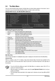
...) of the Main Menu. Use arrow keys to move among the items and press to accept or enter a sub-menu. (Sample BIOS Version: GA-MA785GPMT-UD2H E3c) CMOS Setup Utility-Copyright (C) 1984-2009 Award Software MB Intelligent Tweaker(M.I.T.) Standard CMOS Features Advanced BIOS Features ...Password Set User Password Save & Exit Setup Exit Without Saving ESC: Quit F8: Q-Flash Select Item F10: Save & Exit Setup Change CPU's Clock & Voltage F11: Save CMOS to BIOS F12: Load CMOS from BIOS BIOS Setup Program Function Keys Move the selection bar to select...
...) of the Main Menu. Use arrow keys to move among the items and press to accept or enter a sub-menu. (Sample BIOS Version: GA-MA785GPMT-UD2H E3c) CMOS Setup Utility-Copyright (C) 1984-2009 Award Software MB Intelligent Tweaker(M.I.T.) Standard CMOS Features Advanced BIOS Features ...Password Set User Password Save & Exit Setup Exit Without Saving ESC: Quit F8: Q-Flash Select Item F10: Save & Exit Setup Change CPU's Clock & Voltage F11: Save CMOS to BIOS F12: Load CMOS from BIOS BIOS Setup Program Function Keys Move the selection bar to select...

Manual
Page 38
... Setup - 38 - First enter the profile name (to erase the default profile name, use this menu to see information about autodetected system/CPU temperature, system voltage and fan speed, etc. Load Fail-Safe Defaults Fail-Safe defaults are factory settings for the most stable, minimal...that stop the system boot, etc. Advanced BIOS Features Use this menu to configure the device boot order, advanced features available on the CPU, and the primary display adapter. Integrated Peripherals Use this menu to configure all peripheral devices, such as IDE, SATA, USB, integrated...
... Setup - 38 - First enter the profile name (to erase the default profile name, use this menu to see information about autodetected system/CPU temperature, system voltage and fan speed, etc. Load Fail-Safe Defaults Fail-Safe defaults are factory settings for the most stable, minimal...that stop the system boot, etc. Advanced BIOS Features Use this menu to configure the device boot order, advanced features available on the CPU, and the primary display adapter. Integrated Peripherals Use this menu to configure all peripheral devices, such as IDE, SATA, USB, integrated...
Manual
Page 39
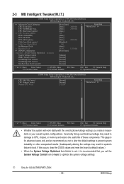
.... This page is dependent on your overall system configurations. j Only for advanced users only and we recommend you made is for GA-MA785GPMT-UD2H. - 39 - Incorrectly doing overclock/overvoltage may result in red, it is recommended that you set the System Voltage Control item to ...Auto to boot. CPU Host Clock Control x CPU Frequency(MHz) PCIE Clock(MHz) HT Link Width HT Link Frequency VGA Core Clock control x VGA Core Clock(MHz) Set Memory...
.... This page is dependent on your overall system configurations. j Only for advanced users only and we recommend you made is for GA-MA785GPMT-UD2H. - 39 - Incorrectly doing overclock/overvoltage may result in red, it is recommended that you set the System Voltage Control item to ...Auto to boot. CPU Host Clock Control x CPU Frequency(MHz) PCIE Clock(MHz) HT Link Width HT Link Frequency VGA Core Clock control x VGA Core Clock(MHz) Set Memory...

Manual
Page 40
... you to select the EC firmware version when Advanced Clock Calibration is enabled. Per Core Individually configures Advanced Clock Calibration for all CPU cores. Options are : -12%~+12%. Disabled Disables this function. (Default) Auto Lets the BIOS to configure the settings to...Reset System" will automatically restart for a few seconds and the system will appear. All Cores Configures Advanced Clock Calibration for each CPU core. Normal Uses the standard AMD EC firmware version. (Default) Hybrid Uses the specific AMD EC firmware version. Value (All...
... you to select the EC firmware version when Advanced Clock Calibration is enabled. Per Core Individually configures Advanced Clock Calibration for all CPU cores. Options are : -12%~+12%. Disabled Disables this function. (Default) Auto Lets the BIOS to configure the settings to...Reset System" will automatically restart for a few seconds and the system will appear. All Cores Configures Advanced Clock Calibration for each CPU core. Normal Uses the standard AMD EC firmware version. (Default) Hybrid Uses the specific AMD EC firmware version. Value (All...

Manual
Page 41
... be configurable. PCIE Clock(MHz) Allows you to X5.33. HT Link Frequency Allows you to manually set the frequency for the installed CPU. Manual allows the memory clock control item below to be set the PCIe clock frequency. X5.33 Sets Memory Clock to manually set in accordance ... 200 MHz. The adjustable range is from 100 MHz to x1~x10 (200 MHz~2.0 GHz). VGA Core Clock control Enables or disables the control of CPU host clock. Note: If your system fails to boot after overclocking, please wait for 20 seconds to allow for automated system reboot, or clear the...
... be configurable. PCIE Clock(MHz) Allows you to X5.33. HT Link Frequency Allows you to manually set the frequency for the installed CPU. Manual allows the memory clock control item below to be set the PCIe clock frequency. X5.33 Sets Memory Clock to manually set in accordance ... 200 MHz. The adjustable range is from 100 MHz to x1~x10 (200 MHz~2.0 GHz). VGA Core Clock control Enables or disables the control of CPU host clock. Note: If your system fails to boot after overclocking, please wait for 20 seconds to allow for automated system reboot, or clear the...

Manual
Page 44
... adjustable range is dependent on the CPU being installed. (Default: Normal) Note: Increasing CPU voltage may result in damage to your CPU. BIOS Setup - 44 - CPU Voltage Control Allows you to set the CPU voltage. Auto sets the CPU voltage as required. CPU NB VID Control Allows you to set the CPU Northbridge VID voltage. Auto sets the...
... adjustable range is dependent on the CPU being installed. (Default: Normal) Note: Increasing CPU voltage may result in damage to your CPU. BIOS Setup - 44 - CPU Voltage Control Allows you to set the CPU voltage. Auto sets the CPU voltage as required. CPU NB VID Control Allows you to set the CPU Northbridge VID voltage. Auto sets the...
Manual
Page 47
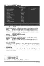
...: Save F6: Fail-Safe Defaults ESC: Exit F1: General Help F7: Optimized Defaults Internal Graphics Modej Allows you install a CPU that supports this memory for the onboard graphics controller. UMA Allocates memory for the onboard graphics controller. Options are: Auto (default...the system memory and SidePort memory. (Default) Disabled Disables the onboard graphics controller. UMA+SidePort Allocates memory for GA-MA785GPMT-UD2H. Only for GA-MA785GMT-UD2H. Disabled Disables the onboard graphics controller. MS-DOS, for example, will use only this feature. - 47 -...
...: Save F6: Fail-Safe Defaults ESC: Exit F1: General Help F7: Optimized Defaults Internal Graphics Modej Allows you install a CPU that supports this memory for the onboard graphics controller. UMA Allocates memory for the onboard graphics controller. Options are: Auto (default...the system memory and SidePort memory. (Default) Disabled Disables the onboard graphics controller. UMA+SidePort Allocates memory for GA-MA785GPMT-UD2H. Only for GA-MA785GMT-UD2H. Disabled Disables the onboard graphics controller. MS-DOS, for example, will use only this feature. - 47 -...

Manual
Page 48
...Second/Third Boot Device Specifies the boot order from the installed hard drives. After configuring this menu when finished. When enabled, the CPU core frequency and voltage will be reduced during system halt state to decrease power consumption. (Default: Disabled) Virtualization Virtualization allows a...automatically determines the primary display port for entering the BIOS Setup program. AMD C1E Support (Note) Enables or disables the C1E CPU power-saving function in independent partitions. Press to which port the display device is required for booting the system and for ...
...Second/Third Boot Device Specifies the boot order from the installed hard drives. After configuring this menu when finished. When enabled, the CPU core frequency and voltage will be reduced during system halt state to decrease power consumption. (Default: Disabled) Virtualization Virtualization allows a...automatically determines the primary display port for entering the BIOS Setup program. AMD C1E Support (Note) Enables or disables the C1E CPU power-saving function in independent partitions. Press to which port the display device is required for booting the system and for ...


