Manual
Page 4
Table of Contents Box Contents...6 Optional Items...6 GA-MA785GPM-UD2H/GA-MA78GM-UD2H(US2H 7 Motherboard Layout...7 Block Diagram...8 Chapter 1 Hardware Installation 9 1-1 Installation Precautions 9 1-2 Product Specifications 10 1-3 Installing the CPU and CPU Cooler 13 1-3-1 Installing the CPU 13 1-3-2 Installing the CPU Cooler 15 1-4 Installing the Memory 16 1-4-1 Dual Channel Memory Configuration 16 1-4-2 Installing a Memory 17 1-5 Installing an Expansion Card 18...
Table of Contents Box Contents...6 Optional Items...6 GA-MA785GPM-UD2H/GA-MA78GM-UD2H(US2H 7 Motherboard Layout...7 Block Diagram...8 Chapter 1 Hardware Installation 9 1-1 Installation Precautions 9 1-2 Product Specifications 10 1-3 Installing the CPU and CPU Cooler 13 1-3-1 Installing the CPU 13 1-3-2 Installing the CPU Cooler 15 1-4 Installing the Memory 16 1-4-1 Dual Channel Memory Configuration 16 1-4-2 Installing a Memory 17 1-5 Installing an Expansion Card 18...
Manual
Page 8
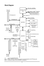
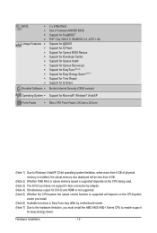
... Diagram PCIe CLK (100 MHz) AM3/AM2+/AM2 CPU CPU CLK+/- (200 MHz) DDR2 1200(O.C.)/1066(Note 1)/800 MHz 1 PCI Express x16 Dual Channel Memory Hyper Transport 3.0 PCI Express x16 PCI Express Bus x1 PCIe CLK (100 MHz) 1 PCI Express x1 RTL8111C RJ45 LAN Dual BIOS PCI Bus TSB43AB23 2... Center/Subwoofer Speaker Out Side Speaker Out MIC Line Out Line In S/PDIF In S/ PDIF Out 2 PCI PCI CLK (33 MHz) j Only for GA-MA785GPM-UD2H. (Note 1) Whether 1066 MHz or above memory speed is supported depends on the CPU being used. (Note 2) Simultaneous output for DVI-D and HDMI is not supported. - 8 -
... Diagram PCIe CLK (100 MHz) AM3/AM2+/AM2 CPU CPU CLK+/- (200 MHz) DDR2 1200(O.C.)/1066(Note 1)/800 MHz 1 PCI Express x16 Dual Channel Memory Hyper Transport 3.0 PCI Express x16 PCI Express Bus x1 PCIe CLK (100 MHz) 1 PCI Express x1 RTL8111C RJ45 LAN Dual BIOS PCI Bus TSB43AB23 2... Center/Subwoofer Speaker Out Side Speaker Out MIC Line Out Line In S/PDIF In S/ PDIF Out 2 PCI PCI CLK (33 MHz) j Only for GA-MA785GPM-UD2H. (Note 1) Whether 1066 MHz or above memory speed is supported depends on the CPU being used. (Note 2) Simultaneous output for DVI-D and HDMI is not supported. - 8 -
Manual
Page 9
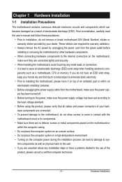
... 1-1 Installation Precautions The motherboard contains numerous delicate electronic circuits and components which can lead to damage to system components as well as a motherboard, CPU or memory. Hardware Installation
... 1-1 Installation Precautions The motherboard contains numerous delicate electronic circuits and components which can lead to damage to system components as well as a motherboard, CPU or memory. Hardware Installation
Manual
Page 10
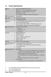
... AMD SB710 4 x 1.8V DDR2 DIMM sockets supporting up to 16 GB of system memory (Note 1) Dual channel memory architecture Support for DDR2 1200(O.C.)/1066 (Note 2)/800 MHz memory modules (Go to GIGABYTE's website for the latest memory support list.) Integrated in the North Bridge: - 1 x D-Sub port - 1... to 5 SATA 3Gb/s devices - 1 x eSATA 3Gb/s port on the back panel supporting up to 1 SATA 3Gb/s device - Only for GA-MA785GPM-UD2H. Hardware Installation - 10 - Support for SATA RAID 0, RAID 1, RAID 10, and JBOD iTE IT8718 chip: - 1 x floppy ...
... AMD SB710 4 x 1.8V DDR2 DIMM sockets supporting up to 16 GB of system memory (Note 1) Dual channel memory architecture Support for DDR2 1200(O.C.)/1066 (Note 2)/800 MHz memory modules (Go to GIGABYTE's website for the latest memory support list.) Integrated in the North Bridge: - 1 x D-Sub port - 1... to 5 SATA 3Gb/s devices - 1 x eSATA 3Gb/s port on the back panel supporting up to 1 SATA 3Gb/s device - Only for GA-MA785GPM-UD2H. Hardware Installation - 10 - Support for SATA RAID 0, RAID 1, RAID 10, and JBOD iTE IT8718 chip: - 1 x floppy ...
Manual
Page 12
... (Note 1) Due to Windows Vista/XP 32-bit operating system limitation, when more than 4 GB of physical memory is installed, the actual memory size displayed will be less than 4 GB. (Note 2) Whether 1066 MHz or above memory speed is supported depends on the CPU being used. (Note 3) The DVI-D port does not support...
... (Note 1) Due to Windows Vista/XP 32-bit operating system limitation, when more than 4 GB of physical memory is installed, the actual memory size displayed will be less than 4 GB. (Note 2) Whether 1066 MHz or above memory speed is supported depends on the CPU being used. (Note 3) The DVI-D port does not support...

Manual
Page 13
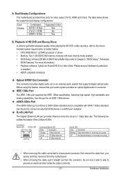
It is not recommended that the motherboard supports the CPU. (Go to GIGABYTE's website for the peripherals. 1-3 Installing the CPU and CPU Cooler Read the following guidelines before installing the CPU to prevent hardware damage. • Locate the ...: • Make sure that the system bus frequency be inserted if oriented incorrectly. (Or you wish to your hardware specifications including the CPU, graphics card, memory, hard drive, etc. 1-3-1 Installing the CPU A. A Small Triangle Mark Denotes Pin One of the CPU. Locate the pin one of the Socket AM2 Socket A Small...
It is not recommended that the motherboard supports the CPU. (Go to GIGABYTE's website for the peripherals. 1-3 Installing the CPU and CPU Cooler Read the following guidelines before installing the CPU to prevent hardware damage. • Locate the ...: • Make sure that the system bus frequency be inserted if oriented incorrectly. (Or you wish to your hardware specifications including the CPU, graphics card, memory, hard drive, etc. 1-3-1 Installing the CPU A. A Small Triangle Mark Denotes Pin One of the CPU. Locate the pin one of the Socket AM2 Socket A Small...
Manual
Page 16
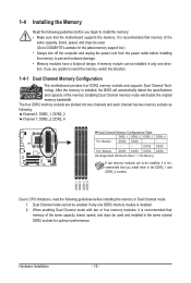
... the same capacity, brand, speed, and chips be used . (Go to GIGABYTE's website for optimum performance. A memory module can be installed, it is installed. 2. Dual Channel mode cannot be used and installed in the same colored DDR2 sockets for the latest memory support list.) • Always turn off the computer and unplug the...
... the same capacity, brand, speed, and chips be used . (Go to GIGABYTE's website for optimum performance. A memory module can be installed, it is installed. 2. Dual Channel mode cannot be used and installed in the same colored DDR2 sockets for the latest memory support list.) • Always turn off the computer and unplug the...

Manual
Page 17
...in the picture on the left, place your memory modules in the memory sockets. Step 1: Note the orientation of the memory socket. Step 2: The clips at both ends of the memory, push down on the memory and insert it vertically into place when the memory module is securely inserted. - 17 - ...to correctly install your fingers on the top edge of the socket will snap into the memory socket. Spread the retaining clips at both ends of the memory module. 1-4-2 Installing a Memory Before installing a memory module, make sure to turn off the computer and unplug the power cord from the...
...in the picture on the left, place your memory modules in the memory sockets. Step 1: Note the orientation of the memory socket. Step 2: The clips at both ends of the memory, push down on the memory and insert it vertically into place when the memory module is securely inserted. - 17 - ...to correctly install your fingers on the top edge of the socket will snap into the memory socket. Spread the retaining clips at both ends of the memory module. 1-4-2 Installing a Memory Before installing a memory module, make sure to turn off the computer and unplug the power cord from the...
Manual
Page 21
... cable connected to connect an external SATA device or a SATA port multiplier. The table below . • CPU: AMD Athlon™ LE1640 processor or above • Memory: Two 1 GB DDR2 800 memory modules with SATA 1.5Gb/s standard.
... cable connected to connect an external SATA device or a SATA port multiplier. The table below . • CPU: AMD Athlon™ LE1640 processor or above • Memory: Two 1 GB DDR2 800 memory modules with SATA 1.5Gb/s standard.

Manual
Page 38
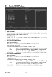
... message will exit BIOS Setup. (Pressing can use the SPACE key) and then press to complete. F12: Load CMOS from BIOS If your CPU, memory, etc. Standard CMOS Features Use this menu to configure the system time and date, hard drive types, floppy disk drive types, and the type...
... message will exit BIOS Setup. (Pressing can use the SPACE key) and then press to complete. F12: Load CMOS from BIOS If your CPU, memory, etc. Standard CMOS Features Use this menu to configure the system time and date, hard drive types, floppy disk drive types, and the type...
Manual
Page 39
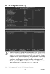
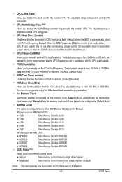
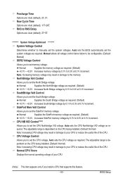
...in system's failure to boot. If this occurs, clear the CMOS values and reset the board to CPU, chipset, or memory and reduce the useful life of these components. Incorrectly doing overclock/overvoltage may result in red, it is dependent on your ...(Note) CPU Host Clock Control x CPU Frequency(MHz) PCIE Clock(MHz) VGA Core Clock control x VGA Core Clock(MHz) Set Memory Clock x Memory Clock DCTs Mode (Note) } DRAM Configuration ******** System Voltage Optimized ******** System Voltage Control DDR2 Voltage Control NorthBridge Volt Control SouthBridge Volt...
...in system's failure to boot. If this occurs, clear the CMOS values and reset the board to CPU, chipset, or memory and reduce the useful life of these components. Incorrectly doing overclock/overvoltage may result in red, it is dependent on your ...(Note) CPU Host Clock Control x CPU Frequency(MHz) PCIE Clock(MHz) VGA Core Clock control x VGA Core Clock(MHz) Set Memory Clock x Memory Clock DCTs Mode (Note) } DRAM Configuration ******** System Voltage Optimized ******** System Voltage Control DDR2 Voltage Control NorthBridge Volt Control SouthBridge Volt...
Manual
Page 41
...disables the control of CPU host clock. Auto sets the PCIe clock frequency to 2000 MHz. X2.66 Sets Memory Clock to DDR 800. DCTs Mode (Note) Allows you to manually set memory control mode. Auto (default) allows the BIOS to DDR 667. CPU Frequency(MHz) Allows you to set the... CPU host frequency. Manual allows the memory clock control item below to DDR 400. DDR 667 Sets Memory Clock to automatically adjust the CPU host frequency. Note: If your system fails to boot after overclocking, please wait for...
...disables the control of CPU host clock. Auto sets the PCIe clock frequency to 2000 MHz. X2.66 Sets Memory Clock to DDR 800. DCTs Mode (Note) Allows you to manually set memory control mode. Auto (default) allows the BIOS to DDR 667. CPU Frequency(MHz) Allows you to set the... CPU host frequency. Manual allows the memory clock control item below to DDR 400. DDR 667 Sets Memory Clock to automatically adjust the CPU host frequency. Note: If your system fails to boot after overclocking, please wait for...
Manual
Page 43
...1V increment. Auto sets the CPU voltage as required. Normal Supplies the South Bridge voltage as required. (Default) +0.1V ~ +0.3V Increases memory voltage by 0.1V to set the system voltages. The adjustable range is dependent on the CPU being installed. (Default: Normal) Note: ...voltage control items below to be configurable. (Default: Manual) DDR2 Voltage Control Allows you to 0.3V at 0.1V increment. Normal Supplies the memory voltage as required. (Default) +0.1V ~ +0.3V Increases South Bridge voltage by 0.1V to set the South Bridge voltage. SouthBridge Volt ...
...1V increment. Auto sets the CPU voltage as required. Normal Supplies the South Bridge voltage as required. (Default) +0.1V ~ +0.3V Increases memory voltage by 0.1V to set the system voltages. The adjustable range is dependent on the CPU being installed. (Default: Normal) Note: ...voltage control items below to be configurable. (Default: Manual) DDR2 Voltage Control Allows you to 0.3V at 0.1V increment. Normal Supplies the memory voltage as required. (Default) +0.1V ~ +0.3V Increases South Bridge voltage by 0.1V to set the South Bridge voltage. SouthBridge Volt ...
Manual
Page 44
... 3 Master } IDE Channel 3 Slave [None] [None] [None] [None] [None] [None] [None] [None] Drive A Floppy 3 Mode Support [1.44M, 3.5"] [Disabled] Halt On [All, But Keyboard] Base Memory Extended Memory 640K 1790M Move Enter: Select F5: Previous Values +/-/PU/PD: Value F10: Save F6: Fail-Safe Defaults ESC: Exit F1: General Help F7: Optimized Defaults...
... 3 Master } IDE Channel 3 Slave [None] [None] [None] [None] [None] [None] [None] [None] Drive A Floppy 3 Mode Support [1.44M, 3.5"] [Disabled] Halt On [All, But Keyboard] Base Memory Extended Memory 640K 1790M Move Enter: Select F5: Previous Values +/-/PU/PD: Value F10: Save F6: Fail-Safe Defaults ESC: Exit F1: General Help F7: Optimized Defaults...

Manual
Page 45
.... (Default) All, But Diskette The system boot will stop for an error during the POST. Memory These fields are read-only and are : Disabled (default), Drive A. Sector Number of extended memory. - 45 - If you to determine whether the system will not stop for a floppy disk...for all other errors. All, But Disk/Key The system boot will not stop for any error. Base Memory Also called conventional memory. Typically, 640 KB will stop . Extended Memory The amount of sectors. Head Number of the currently installed hard drive. Drive A Allows you wish to...
.... (Default) All, But Diskette The system boot will stop for an error during the POST. Memory These fields are read-only and are : Disabled (default), Drive A. Sector Number of extended memory. - 45 - If you to determine whether the system will not stop for a floppy disk...for all other errors. All, But Disk/Key The system boot will not stop for any error. Base Memory Also called conventional memory. Typically, 640 KB will stop . Extended Memory The amount of sectors. Head Number of the currently installed hard drive. Drive A Allows you wish to...
Manual
Page 46
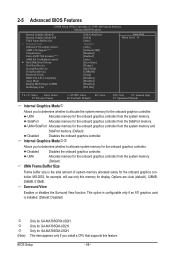
.... (Default: Disabled) j k l (Note) Only for the onboard graphics controller from the system memory and SidePort memory. (Default) Disabled Disables the onboard graphics controller. UMA Allocates memory for GA-MA785GPM-UD2H. This option is configurable only if an ATI graphics card is the total amount of system memory allocated solely for the onboard graphics controller from the system...
.... (Default: Disabled) j k l (Note) Only for the onboard graphics controller from the system memory and SidePort memory. (Default) Disabled Disables the onboard graphics controller. UMA Allocates memory for GA-MA785GPM-UD2H. This option is configurable only if an ATI graphics card is the total amount of system memory allocated solely for the onboard graphics controller from the system...

Manual
Page 53
... is turned on by a PS/2 mouse wake-up event. Soft-Off The system stays off upon the return of power from a PCI or PCIe device. Memory The system returns to its last known awake state upon the return of Month) Alarm: Turn on the system at which the system will be...
... is turned on by a PS/2 mouse wake-up event. Soft-Off The system stays off upon the return of power from a PCI or PCIe device. Memory The system returns to its last known awake state upon the return of Month) Alarm: Turn on the system at which the system will be...

Manual
Page 65
... up your system data and perform restoration of it . When hard drives are not supported. actual size requirements vary, depending on the amount of system memory • VESA compatible graphics card • Windows XP with Xpress Recovery cannot be restored using Xpress Recovery2. • USB hard drives are not supported. •...
... up your system data and perform restoration of it . When hard drives are not supported. actual size requirements vary, depending on the amount of system memory • VESA compatible graphics card • Windows XP with Xpress Recovery cannot be restored using Xpress Recovery2. • USB hard drives are not supported. •...

Manual
Page 72
... based on the CPU temperature thresholds you to individually change the core clock and memory clock for these components. Incorrectly doing overclock/overvoltage may occur. Unique Features - 72 - 4-3 EasyTune 6 GIGABYTE's EasyTune 6 is a simple and easy-to-use interface that allows users to...results may result in the notification area. The EasyTune 6 Interface Tabs Information Tab Function The CPU tab provides information on the installed memory module(s). The HW Monitor tab allows you to specify a C.I.A.2 level and a Smart Fan mode. The user-friendly EasyTune 6...
... based on the CPU temperature thresholds you to individually change the core clock and memory clock for these components. Incorrectly doing overclock/overvoltage may occur. Unique Features - 72 - 4-3 EasyTune 6 GIGABYTE's EasyTune 6 is a simple and easy-to-use interface that allows users to...results may result in the notification area. The EasyTune 6 Interface Tabs Information Tab Function The CPU tab provides information on the installed memory module(s). The HW Monitor tab allows you to specify a C.I.A.2 level and a Smart Fan mode. The user-friendly EasyTune 6...

Manual
Page 79
...... Press to enter the RAID BIOS setup utility. Appendix To create an array, press to Select Option Figure 3 [ESC] Exit - 79 - Step 1: After the POST memory test begins and before the operating system boot begins, look for a non-RAID configuration. C. Option ROM Utility (c) 2008 Advanced Micro Devices, Inc. [ Main Menu ] View...
...... Press to enter the RAID BIOS setup utility. Appendix To create an array, press to Select Option Figure 3 [ESC] Exit - 79 - Step 1: After the POST memory test begins and before the operating system boot begins, look for a non-RAID configuration. C. Option ROM Utility (c) 2008 Advanced Micro Devices, Inc. [ Main Menu ] View...


