
Manual
Page 12
... metal lever back into its original position. Once the CPU is installed on the socket as shown in Fig. 2. Please use , otherwise overheating and permanent damage of the CPU may occur. 5. Please set beyond the proper specifications, please do so according to your hardware specifications including... (90o to the plane of the motherboard) prior to see that none are bent. Fig.1 Socket Lever Position lever at a 90 degree angle. GA-M61SME-S2 Motherboard - 12 - Please make sure the CPU cooler is positioned into its socket, place one finger down on the socket and CPU. Please add...
... metal lever back into its original position. Once the CPU is installed on the socket as shown in Fig. 2. Please use , otherwise overheating and permanent damage of the CPU may occur. 5. Please set beyond the proper specifications, please do so according to your hardware specifications including... (90o to the plane of the motherboard) prior to see that none are bent. Fig.1 Socket Lever Position lever at a 90 degree angle. GA-M61SME-S2 Motherboard - 12 - Please make sure the CPU cooler is positioned into its socket, place one finger down on the socket and CPU. Please add...

Manual
Page 13
... that either thermal tape rather than heat paste be used for detailed installation instructions). Fig.2 Please connect the CPU cooler power connector to prevent CPU overheating. Hardware Installation The CPU cooler may adhere to the cooler manual for heat dissipation or using extreme care when removing the CPU cooler. - 13 - Install...
... that either thermal tape rather than heat paste be used for detailed installation instructions). Fig.2 Please connect the CPU cooler power connector to prevent CPU overheating. Hardware Installation The CPU cooler may adhere to the cooler manual for heat dissipation or using extreme care when removing the CPU cooler. - 13 - Install...
Manual
Page 20
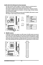
... ground wire (GND). Remember to connect the CPU/system fan cable to the CPU_FAN/SYS_FAN connector to prevent CPU damage or system hanging caused by overheating. 1 CPU_FAN CPU_FAN: Pin No. 1 2 3 4 Definition GND +12V/Speed Control Sense Speed Control 1 SYS_FAN SYS_FAN: Pin No. 1 2 3 Definition GND +12V Sense 5) IDE (IDE... drive or optical drive). Before attaching the IDE cable, please take note of the foolproof groove in the IDE connector. 40 39 GA-M61SME-S2 Motherboard 2 1 - 20 - A red power connector wire indicates a positive connection and requires a +12V power voltage.
... ground wire (GND). Remember to connect the CPU/system fan cable to the CPU_FAN/SYS_FAN connector to prevent CPU damage or system hanging caused by overheating. 1 CPU_FAN CPU_FAN: Pin No. 1 2 3 4 Definition GND +12V/Speed Control Sense Speed Control 1 SYS_FAN SYS_FAN: Pin No. 1 2 3 Definition GND +12V Sense 5) IDE (IDE... drive or optical drive). Before attaching the IDE cable, please take note of the foolproof groove in the IDE connector. 40 39 GA-M61SME-S2 Motherboard 2 1 - 20 - A red power connector wire indicates a positive connection and requires a +12V power voltage.