Manual
Page 1
GA-M52S-S3P AM2 socket motherboard for AMD AthlonTM 64 FX processor/ AMD AthlonTM 64 X2 Dual-Core processor/ AMD AthlonTM 64 processor/AMD SempronTM processor User's Manual Rev. 2001 12ME-M52SS3P-2001R * The WEEE marking on the product indicates this product must not be disposed of with user's other household waste and must be handed over to a designated collection point for the recycling of waste electrical and electronic equipment!! * The WEEE marking applies only in European Union's member states.
GA-M52S-S3P AM2 socket motherboard for AMD AthlonTM 64 FX processor/ AMD AthlonTM 64 X2 Dual-Core processor/ AMD AthlonTM 64 processor/AMD SempronTM processor User's Manual Rev. 2001 12ME-M52SS3P-2001R * The WEEE marking on the product indicates this product must not be disposed of with user's other household waste and must be handed over to a designated collection point for the recycling of waste electrical and electronic equipment!! * The WEEE marking applies only in European Union's member states.
Manual
Page 2
Motherboard GA-M52S-S3P Jul. 12, 2007 Motherboard GA-M52S-S3P Jul. 12, 2007
Motherboard GA-M52S-S3P Jul. 12, 2007 Motherboard GA-M52S-S3P Jul. 12, 2007

Manual
Page 3
... written permission. For product-related information, check on our website at: http://www.gigabyte.com.tw Identifying Your Motherboard Revision The revision number on how to use of GIGABYTE. Example: The logo is 1.0. Check your motherboard looks like this manual are legally registered to the specifications and features in this manual may be reproduced...
... written permission. For product-related information, check on our website at: http://www.gigabyte.com.tw Identifying Your Motherboard Revision The revision number on how to use of GIGABYTE. Example: The logo is 1.0. Check your motherboard looks like this manual are legally registered to the specifications and features in this manual may be reproduced...
Manual
Page 4
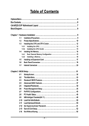
Table of Contents OptionalItems ...6 Box Contents ...6 GA-M52S-S3P Motherboard Layout 7 Block Diagram ...8 Chapter 1 Hardware Installation 9 1-1 Installation Precautions 9 1-2 Product Specifications 10 1-3 Installing the CPU and CPU Cooler 12 1-3-1 Installing the CPU 12 1-3-2 Installing the CPU ...
Table of Contents OptionalItems ...6 Box Contents ...6 GA-M52S-S3P Motherboard Layout 7 Block Diagram ...8 Chapter 1 Hardware Installation 9 1-1 Installation Precautions 9 1-2 Product Specifications 10 1-3 Installing the CPU and CPU Cooler 12 1-3-1 Installing the CPU 12 1-3-2 Installing the CPU ...
Manual
Page 6
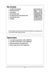
Optional Items 2-port USB 2.0 bracket (Part No. 12CR1-1UB030-51/R) 4-port USB 2.0 bracket (Part No. 12CR1-1UB030-21/R) SATA bracket (Part No.12CF1-3SATPW-11R) S/PDIF in cable (Part No. 12CR1-1SPDIN-01/R) - 6 - The box contents are for reference only and the actual items shall depend on product package you obtain. Box Contents GA-M52S-S3P motherboard Motherboard driver disk User's Manual Quick Installation Guide One IDE cable and one floppy disk drive cable Two SATA 3Gb/s cables I/O Shield The box contents above are subject to change without notice.
Optional Items 2-port USB 2.0 bracket (Part No. 12CR1-1UB030-51/R) 4-port USB 2.0 bracket (Part No. 12CR1-1UB030-21/R) SATA bracket (Part No.12CF1-3SATPW-11R) S/PDIF in cable (Part No. 12CR1-1SPDIN-01/R) - 6 - The box contents are for reference only and the actual items shall depend on product package you obtain. Box Contents GA-M52S-S3P motherboard Motherboard driver disk User's Manual Quick Installation Guide One IDE cable and one floppy disk drive cable Two SATA 3Gb/s cables I/O Shield The box contents above are subject to change without notice.
Manual
Page 7
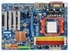
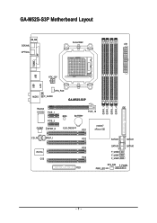
GA-M52S-S3P Motherboard Layout KB_MS COAXIAL Socket AM2 ATX OPTICAL COMA LPT USB USB LAN ATX_12V AUDIO CPU_FAN F_AUDIO GA-M52S-S3P DDRII_1 DDRII_2 DDRII_3 DDRII_4 Realtek 8110SC PCIE_1 IDE PCIE_16 BIOS BATTERY PCIE_2 nVIDIA® CODEC SPDIF_O CLR_CMOS PCI1 nForce 520 CD_IN SPDIF_I IT8716 CI PCI2 PCI3 PCI4 FDD SATAII3 SATAII1 SATAII2 SATAII0 F_USB2 F_USB1 F_USB3 SYS_FAN F_PANEL PWR_LED - 7 -
GA-M52S-S3P Motherboard Layout KB_MS COAXIAL Socket AM2 ATX OPTICAL COMA LPT USB USB LAN ATX_12V AUDIO CPU_FAN F_AUDIO GA-M52S-S3P DDRII_1 DDRII_2 DDRII_3 DDRII_4 Realtek 8110SC PCIE_1 IDE PCIE_16 BIOS BATTERY PCIE_2 nVIDIA® CODEC SPDIF_O CLR_CMOS PCI1 nForce 520 CD_IN SPDIF_I IT8716 CI PCI2 PCI3 PCI4 FDD SATAII3 SATAII1 SATAII2 SATAII0 F_USB2 F_USB1 F_USB3 SYS_FAN F_PANEL PWR_LED - 7 -
Manual
Page 9
... are required for warranty validation. • Always remove the AC power by your hardware components are connected. • To prevent damage to the motherboard, do not allow screws to come in a high-temperature environment. • Turning on the computer power during the installation process can become damaged as... an ESD wrist strap, keep your hands dry and first touch a metal object to eliminate static electricity. • Prior to installing the motherboard, please have it on top of an antistatic pad or within the computer casing. • Do not place the computer system on an ...
... are required for warranty validation. • Always remove the AC power by your hardware components are connected. • To prevent damage to the motherboard, do not allow screws to come in a high-temperature environment. • Turning on the computer power during the installation process can become damaged as... an ESD wrist strap, keep your hands dry and first touch a metal object to eliminate static electricity. • Prior to installing the motherboard, please have it on top of an antistatic pad or within the computer casing. • Do not place the computer system on an ...
Manual
Page 10
...FX processor/AMD AthlonTM 64 X2 Dual-Core processor/ AMD AthlonTM 64 processor/AMD SempronTM processor (Go to GIGABYTE's website for the latest CPU support list.) Front Side Bus Š 2000 MHz FSB Chipset Š... Š Dual channel memory architecture Š Support for DDR2 800/667/533 MHz memory modules (Go to GIGABYTE's website for the latest memory support list.) Audio Š Realtek ALC888 codec Š High Definition Audio &#... S/PDIF Out header Š 3 x USB 2.0/1.1 headers Š 1 x chassis intrusion header Š 1 x power LED header GA-M52S-S3P Motherboard - 10 -
...FX processor/AMD AthlonTM 64 X2 Dual-Core processor/ AMD AthlonTM 64 processor/AMD SempronTM processor (Go to GIGABYTE's website for the latest CPU support list.) Front Side Bus Š 2000 MHz FSB Chipset Š... Š Dual channel memory architecture Š Support for DDR2 800/667/533 MHz memory modules (Go to GIGABYTE's website for the latest memory support list.) Audio Š Realtek ALC888 codec Š High Definition Audio &#... S/PDIF Out header Š 3 x USB 2.0/1.1 headers Š 1 x chassis intrusion header Š 1 x power LED header GA-M52S-S3P Motherboard - 10 -

Manual
Page 11
.... (Note 2) Whether the CPU fan speed control function is supported will depend on the CPU you install. (Note 3) Available functions in Easytune may differ by motherboard model. - 11 - Hardware Installation
.... (Note 2) Whether the CPU fan speed control function is supported will depend on the CPU you install. (Note 3) Available functions in Easytune may differ by motherboard model. - 11 - Hardware Installation
Manual
Page 12
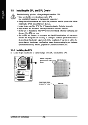
... requirements for the latest CPU support list.) • Always turn on the computer if the CPU cooler is not recom- mended that the motherboard supports the CPU. (Go to GIGABYTE's website for the peripherals. A Small Triangle Mark Denotes Pin One of the CPU. If you begin to prevent hardware damage. • Locate... the CPU socket and the CPU. Locate the pin one of the Socket AM2 CPU Socket A Small Triangle Marking Denotes CPU Pin One AM2 CPU GA-M52S-S3P Motherboard - 12 -
... requirements for the latest CPU support list.) • Always turn on the computer if the CPU cooler is not recom- mended that the motherboard supports the CPU. (Go to GIGABYTE's website for the peripherals. A Small Triangle Mark Denotes Pin One of the CPU. If you begin to prevent hardware damage. • Locate... the CPU socket and the CPU. Locate the pin one of the Socket AM2 CPU Socket A Small Triangle Marking Denotes CPU Pin One AM2 CPU GA-M52S-S3P Motherboard - 12 -
Manual
Page 13
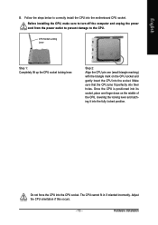
... socket, place one (small triangle marking) with the triangle mark on the middle of the CPU, lowering the locking lever and latching it into the motherboard CPU socket. English B. Follow the steps below to the CPU. Adjust the CPU orientation if this occurs. - 13 -
... socket, place one (small triangle marking) with the triangle mark on the middle of the CPU, lowering the locking lever and latching it into the motherboard CPU socket. English B. Follow the steps below to the CPU. Adjust the CPU orientation if this occurs. - 13 -
Manual
Page 14
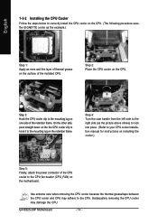
... straight down on the the CPU cooler clip to hook it to correctly install the CPU cooler on the CPU. (The following procedure uses the GIGABYTE cooler as the picture above shows) to lock into place. (Refer to your CPU cooler installation manual for instructions on installing the cooler.) Step 5:... the steps below to the mounting lug on the retention frame. Step 3: Hook the CPU cooler clip to the CPU fan header (CPU_FAN) on the motherboard. GA-M52S-S3P Motherboard - 14 - Step 4: Turn the cam handle from the left side to the right side (as the example.) Step 1: Apply an even and thin layer...
... straight down on the the CPU cooler clip to hook it to correctly install the CPU cooler on the CPU. (The following procedure uses the GIGABYTE cooler as the picture above shows) to lock into place. (Refer to your CPU cooler installation manual for instructions on installing the cooler.) Step 5:... the steps below to the mounting lug on the retention frame. Step 3: Hook the CPU cooler clip to the CPU fan header (CPU_FAN) on the motherboard. GA-M52S-S3P Motherboard - 14 - Step 4: Turn the cam handle from the left side to the right side (as the example.) Step 1: Apply an even and thin layer...

Manual
Page 15
...to CPU limitation, read the following guidelines before installing the memory to insert the memory, switch the direction. 1-4-1 Dual Channel Memory Configuration This motherboard provides four DDR2 memory sockets and supports Dual Channel Technology. When enabling Dual Channel mode with two or four memory modules, it is recommended...are to install the memory: • Make sure that memory of the same capacity, brand, speed, and chips be used . (Go to GIGABYTE's website for optimum performance. - 15 - If you install them in only one DDR2 memory module is recommended that the...
...to CPU limitation, read the following guidelines before installing the memory to insert the memory, switch the direction. 1-4-1 Dual Channel Memory Configuration This motherboard provides four DDR2 memory sockets and supports Dual Channel Technology. When enabling Dual Channel mode with two or four memory modules, it is recommended...are to install the memory: • Make sure that memory of the same capacity, brand, speed, and chips be used . (Go to GIGABYTE's website for optimum performance. - 15 - If you install them in only one DDR2 memory module is recommended that the...

Manual
Page 16
... the left, place your memory modules in one direction. Spread the retaining clips at both ends of the socket will snap into the memory socket. GA-M52S-S3P Motherboard - 16 - Notch DDR2 DIMM A DDR2 memory module has a notch, so it vertically into place when the memory module is securely inserted. Follow the steps below...
... the left, place your memory modules in one direction. Spread the retaining clips at both ends of the socket will snap into the memory socket. GA-M52S-S3P Motherboard - 16 - Notch DDR2 DIMM A DDR2 memory module has a notch, so it vertically into place when the memory module is securely inserted. Follow the steps below...

Manual
Page 17
... with the slot, and press down on your operating system. If necessary, go to BIOS Setup to install an expansion card: • Make sure the motherboard supports the expansion card. Carefully read the manual that supports your expansion card(s). 7. Turn on the card until it is locked by the latch at...
... with the slot, and press down on your operating system. If necessary, go to BIOS Setup to install an expansion card: • Make sure the motherboard supports the expansion card. Carefully read the manual that supports your expansion card(s). 7. Turn on the card until it is locked by the latch at...
Manual
Page 18
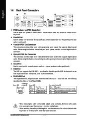
Use this feature, ensure that your device and then remove it from the motherboard. • When removing the cable, pull it side to side to an external audio system that supports digital coaxial audio. Before using this feature, ensure ... describes the states of the LAN port LEDs. Do not rock it straight out from your audio system provides an optical digital audio in connector. GA-M52S-S3P Motherboard - 18 -
Use this feature, ensure that your device and then remove it from the motherboard. • When removing the cable, pull it side to side to an external audio system that supports digital coaxial audio. Before using this feature, ensure ... describes the states of the LAN port LEDs. Do not rock it straight out from your audio system provides an optical digital audio in connector. GA-M52S-S3P Motherboard - 18 -

Manual
Page 20
... device and before connecting external devices: • First make sure the device cable has been securely attached to turn off the devices and your computer. GA-M52S-S3P Motherboard - 20 - English 1-7 Internal Connectors 2 1 3 11 9 17 14 12 13 16 1) ATX_12V 2) ATX (Power Connector) 3) CPU_FAN 4) SYS_FAN 5) FDD 6) IDE 7) SATAII0 / 1 / 2 / 3 8) PWR_LED 9) BATTERY 6 7 15 10 5 84 10..., make sure your devices are compliant with the connectors you wish to connect. • Before installing the devices, be sure to the connector on the motherboard.
... device and before connecting external devices: • First make sure the device cable has been securely attached to turn off the devices and your computer. GA-M52S-S3P Motherboard - 20 - English 1-7 Internal Connectors 2 1 3 11 9 17 14 12 13 16 1) ATX_12V 2) ATX (Power Connector) 3) CPU_FAN 4) SYS_FAN 5) FDD 6) IDE 7) SATAII0 / 1 / 2 / 3 8) PWR_LED 9) BATTERY 6 7 15 10 5 84 10..., make sure your devices are compliant with the connectors you wish to connect. • Before installing the devices, be sure to the connector on the motherboard.
Manual
Page 21
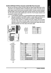
... power supply cable into pins under the protective cover when using a 2x12 power supply, remove the protective cover from the main power connector on the motherboard. English 1/2) ATX_12V/ATX (2x2 12V Power Connector and 2x12 Main Power Connector) With the use of the power connector, the power supply can supply enough... power, the result can lead to an unstable or unbootable system. • The main power connector is turned off and all the components on the motherboard.
... power supply cable into pins under the protective cover when using a 2x12 power supply, remove the protective cover from the main power connector on the motherboard. English 1/2) ATX_12V/ATX (2x2 12V Power Connector and 2x12 Main Power Connector) With the use of the power connector, the power supply can supply enough... power, the result can lead to an unstable or unbootable system. • The main power connector is turned off and all the components on the motherboard.

Manual
Page 22
...positive connection and requires a +12V voltage. The types of a CPU/system fan with color-coded power connector wires. The motherboard supports CPU/system fan speed control, which requires the use of floppy disk drives supported are not configuration jumper blocks. For... or the system may result in damage to connect it in the correct orientation. Do not place a jumper cap on the connector. 33 1 34 2 GA-M52S-S3P Motherboard - 22 - Most fans are designed with fan speed control design. Definition 1 GND 1 CPU_FAN 2 +12V / Speed Control 3 Sense 4 Speed Control ...
...positive connection and requires a +12V voltage. The types of a CPU/system fan with color-coded power connector wires. The motherboard supports CPU/system fan speed control, which requires the use of floppy disk drives supported are not configuration jumper blocks. For... or the system may result in damage to connect it in the correct orientation. Do not place a jumper cap on the connector. 33 1 34 2 GA-M52S-S3P Motherboard - 22 - Most fans are designed with fan speed control design. Definition 1 GND 1 CPU_FAN 2 +12V / Speed Control 3 Sense 4 Speed Control ...
Manual
Page 24
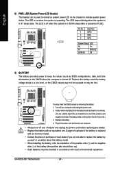
... battery (the positive side should face up). • Used batteries must be handled in the power cord and restart your computer. • Always turn off . GA-M52S-S3P Motherboard - 24 - Gently remove the battery from the battery holder and wait for one . English 8) PWR_LED (System Power LED Header) This header can be lost.
... battery (the positive side should face up). • Used batteries must be handled in the power cord and restart your computer. • Always turn off . GA-M52S-S3P Motherboard - 24 - Gently remove the battery from the battery holder and wait for one . English 8) PWR_LED (System Power LED Header) This header can be lost.


