Manual
Page 1
GA-M52S-S3P AM2 socket motherboard for AMD AthlonTM 64 FX processor/ AMD AthlonTM 64 X2 Dual-Core processor/ AMD AthlonTM 64 processor/AMD SempronTM processor User's Manual Rev. 2001 12ME-M52SS3P-2001R * The WEEE marking on the product indicates this product must not be disposed of with user's other household waste and must be handed over to a designated collection point for the recycling of waste electrical and electronic equipment!! * The WEEE marking applies only in European Union's member states.
GA-M52S-S3P AM2 socket motherboard for AMD AthlonTM 64 FX processor/ AMD AthlonTM 64 X2 Dual-Core processor/ AMD AthlonTM 64 processor/AMD SempronTM processor User's Manual Rev. 2001 12ME-M52SS3P-2001R * The WEEE marking on the product indicates this product must not be disposed of with user's other household waste and must be handed over to a designated collection point for the recycling of waste electrical and electronic equipment!! * The WEEE marking applies only in European Union's member states.
Manual
Page 2
Motherboard GA-M52S-S3P Jul. 12, 2007 Motherboard GA-M52S-S3P Jul. 12, 2007
Motherboard GA-M52S-S3P Jul. 12, 2007 Motherboard GA-M52S-S3P Jul. 12, 2007

Manual
Page 3
... for technical information. Disclaimer Information in any means without prior notice. For example, "REV: 1.0" means the revision of the motherboard is the property of GIGABYTE branded motherboards. GIGABYTE UNITED INC. sive global distributor of GIGABYTE. Changes to use of this manual may be made by GIGA-BYTE TECHNOLOGY CO., LTD. Copyright © 2007 GIGA-BYTE...
... for technical information. Disclaimer Information in any means without prior notice. For example, "REV: 1.0" means the revision of the motherboard is the property of GIGABYTE branded motherboards. GIGABYTE UNITED INC. sive global distributor of GIGABYTE. Changes to use of this manual may be made by GIGA-BYTE TECHNOLOGY CO., LTD. Copyright © 2007 GIGA-BYTE...
Manual
Page 4
Table of Contents OptionalItems ...6 Box Contents ...6 GA-M52S-S3P Motherboard Layout 7 Block Diagram ...8 Chapter 1 Hardware Installation 9 1-1 Installation Precautions 9 1-2 Product Specifications 10 1-3 Installing the CPU and CPU Cooler 12 1-3-1 Installing the CPU 12 1-3-2 Installing the CPU ...
Table of Contents OptionalItems ...6 Box Contents ...6 GA-M52S-S3P Motherboard Layout 7 Block Diagram ...8 Chapter 1 Hardware Installation 9 1-1 Installation Precautions 9 1-2 Product Specifications 10 1-3 Installing the CPU and CPU Cooler 12 1-3-1 Installing the CPU 12 1-3-2 Installing the CPU ...
Manual
Page 6
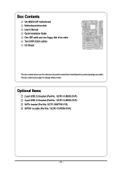
Box Contents GA-M52S-S3P motherboard Motherboard driver disk User's Manual Quick Installation Guide One IDE cable and one floppy disk drive cable Two SATA 3Gb/s cables I/O Shield The box contents above are subject to change without notice. Optional Items 2-port USB 2.0 bracket (Part No. 12CR1-1UB030-51/R) 4-port USB 2.0 bracket (Part No. 12CR1-1UB030-21/R) SATA bracket (Part No.12CF1-3SATPW-11R) S/PDIF in cable (Part No. 12CR1-1SPDIN-01/R) - 6 - The box contents are for reference only and the actual items shall depend on product package you obtain.
Box Contents GA-M52S-S3P motherboard Motherboard driver disk User's Manual Quick Installation Guide One IDE cable and one floppy disk drive cable Two SATA 3Gb/s cables I/O Shield The box contents above are subject to change without notice. Optional Items 2-port USB 2.0 bracket (Part No. 12CR1-1UB030-51/R) 4-port USB 2.0 bracket (Part No. 12CR1-1UB030-21/R) SATA bracket (Part No.12CF1-3SATPW-11R) S/PDIF in cable (Part No. 12CR1-1SPDIN-01/R) - 6 - The box contents are for reference only and the actual items shall depend on product package you obtain.
Manual
Page 7
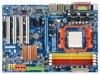
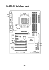
GA-M52S-S3P Motherboard Layout KB_MS COAXIAL Socket AM2 ATX OPTICAL COMA LPT USB USB LAN ATX_12V AUDIO CPU_FAN F_AUDIO GA-M52S-S3P DDRII_1 DDRII_2 DDRII_3 DDRII_4 Realtek 8110SC PCIE_1 IDE PCIE_16 BIOS BATTERY PCIE_2 nVIDIA® CODEC SPDIF_O CLR_CMOS PCI1 nForce 520 CD_IN SPDIF_I IT8716 CI PCI2 PCI3 PCI4 FDD SATAII3 SATAII1 SATAII2 SATAII0 F_USB2 F_USB1 F_USB3 SYS_FAN F_PANEL PWR_LED - 7 -
GA-M52S-S3P Motherboard Layout KB_MS COAXIAL Socket AM2 ATX OPTICAL COMA LPT USB USB LAN ATX_12V AUDIO CPU_FAN F_AUDIO GA-M52S-S3P DDRII_1 DDRII_2 DDRII_3 DDRII_4 Realtek 8110SC PCIE_1 IDE PCIE_16 BIOS BATTERY PCIE_2 nVIDIA® CODEC SPDIF_O CLR_CMOS PCI1 nForce 520 CD_IN SPDIF_I IT8716 CI PCI2 PCI3 PCI4 FDD SATAII3 SATAII1 SATAII2 SATAII0 F_USB2 F_USB1 F_USB3 SYS_FAN F_PANEL PWR_LED - 7 -
Manual
Page 9
... components such as a result of electrostatic discharge (ESD). Hardware Installation These stickers are connected tightly and securely. • When handling the motherboard, avoid touching any installation steps or have a problem related to the use of the product, please consult a certified computer technician. - ..., carefully read the user's manual and follow these procedures: • Prior to installation, do not remove or break motherboard S/N (Serial Number) sticker or warranty sticker provided by unplugging the power cord from the power outlet before installing or removing the...
... components such as a result of electrostatic discharge (ESD). Hardware Installation These stickers are connected tightly and securely. • When handling the motherboard, avoid touching any installation steps or have a problem related to the use of the product, please consult a certified computer technician. - ..., carefully read the user's manual and follow these procedures: • Prior to installation, do not remove or break motherboard S/N (Serial Number) sticker or warranty sticker provided by unplugging the power cord from the power outlet before installing or removing the...
Manual
Page 10
... memory (Note 1) Š Dual channel memory architecture Š Support for DDR2 800/667/533 MHz memory modules (Go to GIGABYTE's website for the latest memory support list.) Audio Š Realtek ALC888 codec Š High Definition Audio Š 2/4/5.1/7.1-channel Š... x S/PDIF In header Š 1 x S/PDIF Out header Š 3 x USB 2.0/1.1 headers Š 1 x chassis intrusion header Š 1 x power LED header GA-M52S-S3P Motherboard - 10 - Support for CD In LAN Š RTL 8110SC chip (10/100/1000 Mbit) Expansion Slots Š 1 x PCI Express x16 slot Š 2 x PCI Express...
... memory (Note 1) Š Dual channel memory architecture Š Support for DDR2 800/667/533 MHz memory modules (Go to GIGABYTE's website for the latest memory support list.) Audio Š Realtek ALC888 codec Š High Definition Audio Š 2/4/5.1/7.1-channel Š... x S/PDIF In header Š 1 x S/PDIF Out header Š 3 x USB 2.0/1.1 headers Š 1 x chassis intrusion header Š 1 x power LED header GA-M52S-S3P Motherboard - 10 - Support for CD In LAN Š RTL 8110SC chip (10/100/1000 Mbit) Expansion Slots Š 1 x PCI Express x16 slot Š 2 x PCI Express...

Manual
Page 11
.... (Note 2) Whether the CPU fan speed control function is supported will depend on the CPU you install. (Note 3) Available functions in Easytune may differ by motherboard model. - 11 - Hardware Installation
.... (Note 2) Whether the CPU fan speed control function is supported will depend on the CPU you install. (Note 3) Available functions in Easytune may differ by motherboard model. - 11 - Hardware Installation
Manual
Page 12
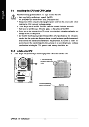
...and unplug the power cord from the power outlet before you wish to set beyond the standard specifications, please do so according to GIGABYTE's website for the peripherals. If you begin to install the CPU: • Make sure that the system bus frequency be ... not installed, otherwise overheating and damage of the Socket AM2 CPU Socket A Small Triangle Marking Denotes CPU Pin One AM2 CPU GA-M52S-S3P Motherboard - 12 - mended that the motherboard supports the CPU. (Go to your hardware specifications including the CPU, graphics card, memory, hard drive, etc. 1-3-1 Installing ...
...and unplug the power cord from the power outlet before you wish to set beyond the standard specifications, please do so according to GIGABYTE's website for the peripherals. If you begin to install the CPU: • Make sure that the system bus frequency be ... not installed, otherwise overheating and damage of the Socket AM2 CPU Socket A Small Triangle Marking Denotes CPU Pin One AM2 CPU GA-M52S-S3P Motherboard - 12 - mended that the motherboard supports the CPU. (Go to your hardware specifications including the CPU, graphics card, memory, hard drive, etc. 1-3-1 Installing ...
Manual
Page 13
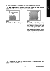
... lift up the CPU socket locking lever. The CPU cannot fit in if oriented incorrectly. Make sure that the CPU pins fit perfectly into the motherboard CPU socket. Adjust the CPU orientation if this occurs. - 13 - Hardware Installation Once the CPU is positioned into its socket, place one (small triangle marking...
... lift up the CPU socket locking lever. The CPU cannot fit in if oriented incorrectly. Make sure that the CPU pins fit perfectly into the motherboard CPU socket. Adjust the CPU orientation if this occurs. - 13 - Hardware Installation Once the CPU is positioned into its socket, place one (small triangle marking...
Manual
Page 14
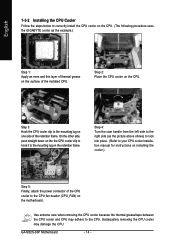
.... English 1-3-2 Installing the CPU Cooler Follow the steps below to correctly install the CPU cooler on the CPU. (The following procedure uses the GIGABYTE cooler as the picture above shows) to lock into place. (Refer to your CPU cooler installation manual for instructions on installing the cooler.) Step...the right side (as the example.) Step 1: Apply an even and thin layer of thermal grease on one side of the retention frame. GA-M52S-S3P Motherboard - 14 - Use extreme care when removing the CPU cooler because the thermal grease/tape between the CPU cooler and CPU may damage the CPU...
.... English 1-3-2 Installing the CPU Cooler Follow the steps below to correctly install the CPU cooler on the CPU. (The following procedure uses the GIGABYTE cooler as the picture above shows) to lock into place. (Refer to your CPU cooler installation manual for instructions on installing the cooler.) Step...the right side (as the example.) Step 1: Apply an even and thin layer of thermal grease on one side of the retention frame. GA-M52S-S3P Motherboard - 14 - Use extreme care when removing the CPU cooler because the thermal grease/tape between the CPU cooler and CPU may damage the CPU...

Manual
Page 15
...capacity, brand, speed, and chips be used . (Go to GIGABYTE's website for optimum performance. - 15 - A memory module can be installed in only one DDR2 memory module is recommended that the motherboard supports the memory. DS/SS DS/SS Four Modules DS/SS ... - - - - - - - DDRII_1 DDRII_2 DDRII_3 DDRII_4 Due to insert the memory, switch the direction. 1-4-1 Dual Channel Memory Configuration This motherboard provides four DDR2 memory sockets and supports Dual Channel Technology. It is installed. 2. English 1-4 Installing the Memory Read the following guidelines before you begin...
...capacity, brand, speed, and chips be used . (Go to GIGABYTE's website for optimum performance. - 15 - A memory module can be installed in only one DDR2 memory module is recommended that the motherboard supports the memory. DS/SS DS/SS Four Modules DS/SS ... - - - - - - - DDRII_1 DDRII_2 DDRII_3 DDRII_4 Due to insert the memory, switch the direction. 1-4-1 Dual Channel Memory Configuration This motherboard provides four DDR2 memory sockets and supports Dual Channel Technology. It is installed. 2. English 1-4 Installing the Memory Read the following guidelines before you begin...

Manual
Page 16
... DIMM A DDR2 memory module has a notch, so it vertically into place when the memory module is securely inserted. GA-M52S-S3P Motherboard - 16 - Follow the steps below to the memory module. Place the memory module on this motherboard. English 1-4-2 Installing a Memory Before installing a memory module , make sure to turn off the computer and unplug the...
... DIMM A DDR2 memory module has a notch, so it vertically into place when the memory module is securely inserted. GA-M52S-S3P Motherboard - 16 - Follow the steps below to the memory module. Place the memory module on this motherboard. English 1-4-2 Installing a Memory Before installing a memory module , make sure to turn off the computer and unplug the...

Manual
Page 17
... chassis cover(s). 6. English 1-5 Installing an Expansion Card Read the following guidelines before installing an expansion card to install an expansion card: • Make sure the motherboard supports the expansion card.
... chassis cover(s). 6. English 1-5 Installing an Expansion Card Read the following guidelines before installing an expansion card to install an expansion card: • Make sure the motherboard supports the expansion card.
Manual
Page 18
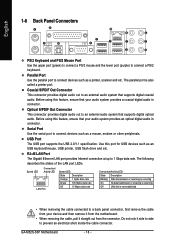
...that supports digital optical audio. Serial Port Use the serial port to a back panel connector, first remove the cable from the connector. GA-M52S-S3P Motherboard - 18 - Coaxial S/PDIF Out Connector This connector provides digital audio out to an external audio system that your device and then remove ...it from the motherboard. • When removing the cable, pull it side to side to 1 Gbps data rate. Before using this feature, ensure that ...
...that supports digital optical audio. Serial Port Use the serial port to a back panel connector, first remove the cable from the connector. GA-M52S-S3P Motherboard - 18 - Coaxial S/PDIF Out Connector This connector provides digital audio out to an external audio system that your device and then remove ...it from the motherboard. • When removing the cable, pull it side to side to 1 Gbps data rate. Before using this feature, ensure that ...

Manual
Page 20
...) F_PANEL 11) F_AUDIO 12) CD_IN 13) SPDIF_I 14) SPDIF_O 15) F_USB1 / F_USB2 / F_USB3 16) CI 17) CLR_CMOS Read the following guidelines before turning on the motherboard. GA-M52S-S3P Motherboard - 20 -
...) F_PANEL 11) F_AUDIO 12) CD_IN 13) SPDIF_I 14) SPDIF_O 15) F_USB1 / F_USB2 / F_USB3 16) CI 17) CLR_CMOS Read the following guidelines before turning on the motherboard. GA-M52S-S3P Motherboard - 20 -
Manual
Page 21
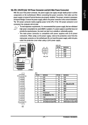
...enough stable power to all devices are properly installed. If a power supply is turned off and all the components on the motherboard. The 12V power connector mainly supplies power to the power connector in the correct orientation. Do not insert the power supply ...cable into pins under the protective cover when using a 2x12 power supply, remove the protective cover from the main power connector on the motherboard. When using a 2x10 power supply. 42 31 ATX_12V ATX_12V: Pin No. 1 2 3 4 Definition GND GND +12V +12V 12 24 1 13 ATX ATX : Pin No. 1 2 3...
...enough stable power to all devices are properly installed. If a power supply is turned off and all the components on the motherboard. The 12V power connector mainly supplies power to the power connector in the correct orientation. Do not insert the power supply ...cable into pins under the protective cover when using a 2x12 power supply, remove the protective cover from the main power connector on the motherboard. When using a 2x10 power supply. 42 31 ATX_12V ATX_12V: Pin No. 1 2 3 4 Definition GND GND +12V +12V 12 24 1 13 ATX ATX : Pin No. 1 2 3...

Manual
Page 22
...to the CPU or the system may result in the correct orientation. Do not place a jumper cap on the connector. 33 1 34 2 GA-M52S-S3P Motherboard - 22 - Before connecting a floppy disk drive, locate the foolproof groove on the headers. 5) FDD (Floppy Disk Drive Connector) This connector... For optimum heat dissipation, it in damage to prevent your CPU and system from overheating. English 3/4) CPU_FAN/SYS_FAN (Fan Headers) The motherboard has a 4-pin CPU fan header (CPU_FAN) and a 3-pin system fan header (SYS_FAN). A red power connector wire indicates a positive connection ...
...to the CPU or the system may result in the correct orientation. Do not place a jumper cap on the connector. 33 1 34 2 GA-M52S-S3P Motherboard - 22 - Before connecting a floppy disk drive, locate the foolproof groove on the headers. 5) FDD (Floppy Disk Drive Connector) This connector... For optimum heat dissipation, it in damage to prevent your CPU and system from overheating. English 3/4) CPU_FAN/SYS_FAN (Fan Headers) The motherboard has a 4-pin CPU fan header (CPU_FAN) and a 3-pin system fan header (SYS_FAN). A red power connector wire indicates a positive connection ...
Manual
Page 24
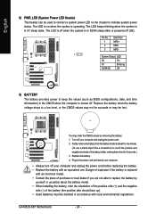
... S3/S4/S5 Off 9) BATTERY The battery provides power to keep the values (such as BIOS configurations, date, and time information) in S1 sleep state. GA-M52S-S3P Motherboard - 24 -
... S3/S4/S5 Off 9) BATTERY The battery provides power to keep the values (such as BIOS configurations, date, and time information) in S1 sleep state. GA-M52S-S3P Motherboard - 24 -


