
User Manual
Page 1
GA-K8N51PVM9-RH-NV AMD Socket 939 Processor Motherboard User's Manual Rev. 1004 12ME-N51PVM9R-1004R * The WEEE marking on the product indicates this product must not be disposed of with user's other household waste and must be handed over to a designated collection point for the recycling of waste electrical and electronic equipment!! * The WEEE marking applies only in European Union's member states.
GA-K8N51PVM9-RH-NV AMD Socket 939 Processor Motherboard User's Manual Rev. 1004 12ME-N51PVM9R-1004R * The WEEE marking on the product indicates this product must not be disposed of with user's other household waste and must be handed over to a designated collection point for the recycling of waste electrical and electronic equipment!! * The WEEE marking applies only in European Union's member states.

User Manual
Page 4
Table of Contents ItemChecklist ...6 OptionalAccessories ...6 GA-K8N51PVM9-RH-NV Motherboard Layout 7 Block Diagram ...8 Chapter 1 Hardware Installation 9 1-1 Considerations Prior to Installation 9 1-2 Feature Summary 10 1-3 Installation of the CPU and CPU Cooler 12 1-3-1 Installation of the ...
Table of Contents ItemChecklist ...6 OptionalAccessories ...6 GA-K8N51PVM9-RH-NV Motherboard Layout 7 Block Diagram ...8 Chapter 1 Hardware Installation 9 1-1 Considerations Prior to Installation 9 1-2 Feature Summary 10 1-3 Installation of the CPU and CPU Cooler 12 1-3-1 Installation of the ...

User Manual
Page 10
... 4 SATA 3Gb/s devices - English 1-2 Feature Summary CPU Š Supports Socket 939 for additional 4 ports by cables Š 1 TPM_CLR connector Š 1 PWR_LED connector Š 1 CI connector GA-K8N51PVM9-RH-NV Motherboard - 10 -
... 4 SATA 3Gb/s devices - English 1-2 Feature Summary CPU Š Supports Socket 939 for additional 4 ports by cables Š 1 TPM_CLR connector Š 1 PWR_LED connector Š 1 CI connector GA-K8N51PVM9-RH-NV Motherboard - 10 -

User Manual
Page 12
... the wrong direction, the CPU will not fit if positioned incorrectly. It is installed on the socket as shown in accordance with the following conditions: 1. GA-K8N51PVM9-RH-NV Motherboard - 12 - Fig.2 Pin 1 location on the CPU.
... the wrong direction, the CPU will not fit if positioned incorrectly. It is installed on the socket as shown in accordance with the following conditions: 1. GA-K8N51PVM9-RH-NV Motherboard - 12 - Fig.2 Pin 1 location on the CPU.

User Manual
Page 14
... at both edges of the DIMM sockets to remove the DIMM module. Reverse the installation steps when you are designed so that the memory used . 2. GA-K8N51PVM9-RH-NV Motherboard - 14 - Insert the DIMM memory module vertically into the DIMM socket. A memory module can be inserted only in only one direction. Memory modules are...
... at both edges of the DIMM sockets to remove the DIMM module. Reverse the installation steps when you are designed so that the memory used . 2. GA-K8N51PVM9-RH-NV Motherboard - 14 - Insert the DIMM memory module vertically into the DIMM socket. A memory module can be inserted only in only one direction. Memory modules are...

User Manual
Page 15
... : 1. All of identical brand, size, chips, and speed. To enable Dual Channel mode with 4 memory modules, it is installed. 2. English Dual Channel Memory Configuration The GA-K8N51PVM9-RH-NV supports the Dual Channel Technology.
... : 1. All of identical brand, size, chips, and speed. To enable Dual Channel mode with 4 memory modules, it is installed. 2. English Dual Channel Memory Configuration The GA-K8N51PVM9-RH-NV supports the Dual Channel Technology.

User Manual
Page 16
... the small whitedrawable bar at the end of the PCI Express x16 slot when you try to secure the slot bracket of the expansion card. 6. GA-K8N51PVM9-RH-NV Motherboard - 16 - Press the expansion card firmly into the computer. 2. Replace your computer's chassis cover, screws and slot bracket from the operating system. To release...
... the small whitedrawable bar at the end of the PCI Express x16 slot when you try to secure the slot bracket of the expansion card. 6. GA-K8N51PVM9-RH-NV Motherboard - 16 - Press the expansion card firmly into the computer. 2. Replace your computer's chassis cover, screws and slot bracket from the operating system. To release...

User Manual
Page 18
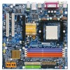
English 1-7 Connectors Introduction 1 3 2 5 11 6 9 17 18 7 12 10 15 16 4 14 13 8 1) ATX_12V 2) ATX (Power Connector) 3) CPU_FAN 4) SYS_FAN 5) FDD 6) IDE1 / IDE2 7) SATAII0_1 / SATAII2_3 8) PWR_LED 9) BATTERY 10) F_PANEL 11) F_AUDIO 12) CD_IN 13) F_USB1 / F_USB2 14) TPM_CLR 15) SPDIF_IO 16) COMA 17) CLR_CMOS 18) CI GA-K8N51PVM9-RH-NV Motherboard - 18 -
English 1-7 Connectors Introduction 1 3 2 5 11 6 9 17 18 7 12 10 15 16 4 14 13 8 1) ATX_12V 2) ATX (Power Connector) 3) CPU_FAN 4) SYS_FAN 5) FDD 6) IDE1 / IDE2 7) SATAII0_1 / SATAII2_3 8) PWR_LED 9) BATTERY 10) F_PANEL 11) F_AUDIO 12) CD_IN 13) F_USB1 / F_USB2 14) TPM_CLR 15) SPDIF_IO 16) COMA 17) CLR_CMOS 18) CI GA-K8N51PVM9-RH-NV Motherboard - 18 -

User Manual
Page 20
The black connector wire is used to connect the FDD cable while the other end of the foolproof groove in the FDD connector. 34 33 2 1 GA-K8N51PVM9-RH-NV Motherboard - 20 - Remember to connect the CPU/system fan cable to the CPU_FAN/SYS_FAN connector to the FDD drive. A red power connector wire indicates a positive ...
The black connector wire is used to connect the FDD cable while the other end of the foolproof groove in the FDD connector. 34 33 2 1 GA-K8N51PVM9-RH-NV Motherboard - 20 - Remember to connect the CPU/system fan cable to the CPU_FAN/SYS_FAN connector to the FDD drive. A red power connector wire indicates a positive ...
User Manual
Page 22
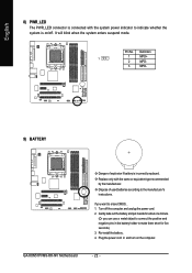
... type recommended by the manufacturer. Definition 1 1 MPD+ 2 MPD- 3 MPD- 9) BATTERY Danger of used batteries according to indicate whether the system is incorrectly replaced. Turn off . GA-K8N51PVM9-RH-NV Motherboard - 22 - Pin No. Plug the power cord in the battery holder to erase CMOS... 1. Replace only with the system power indicator to the manufacturer...
... type recommended by the manufacturer. Definition 1 1 MPD+ 2 MPD- 3 MPD- 9) BATTERY Danger of used batteries according to indicate whether the system is incorrectly replaced. Turn off . GA-K8N51PVM9-RH-NV Motherboard - 22 - Pin No. Plug the power cord in the battery holder to erase CMOS... 1. Replace only with the system power indicator to the manufacturer...

User Manual
Page 24
... about the software settings. 12) CD_IN (CD In Connector) Connect CD-ROM or DVD-ROM audio out to this connector. Definition 1 CD-L 2 GND 3 GND 4 CD-R GA-K8N51PVM9-RH-NV Motherboard - 24 - Incorrect connection between the module and connector will make the audio device unable to support HD Audio. English 11) F_AUDIO (Front Audio Panel...
... about the software settings. 12) CD_IN (CD In Connector) Connect CD-ROM or DVD-ROM audio out to this connector. Definition 1 CD-L 2 GND 3 GND 4 CD-R GA-K8N51PVM9-RH-NV Motherboard - 24 - Incorrect connection between the module and connector will make the audio device unable to support HD Audio. English 11) F_AUDIO (Front Audio Panel...

User Manual
Page 26
For optional SPDIF cable, please contact your nearest dealer for optional COMA cable. 2 10 1 9 Pin No. 1 2 3 4 5 6 7 8 9 10 Definition NDCDANSINA NSOUTA NDTRAGND NDSRANRTSANCTSANRIANo Pin GA-K8N51PVM9-RH-NV Motherboard - 26 - Be careful with the polarity of the COMA connector. Please contact your local dealer. 26 15 Pin No. 1 2 3 4 5 6 Definition Power No Pin SPDIF ...
For optional SPDIF cable, please contact your nearest dealer for optional COMA cable. 2 10 1 9 Pin No. 1 2 3 4 5 6 7 8 9 10 Definition NDCDANSINA NSOUTA NDTRAGND NDSRANRTSANCTSANRIANo Pin GA-K8N51PVM9-RH-NV Motherboard - 26 - Be careful with the polarity of the COMA connector. Please contact your local dealer. 26 15 Pin No. 1 2 3 4 5 6 Definition Power No Pin SPDIF ...

User Manual
Page 30
...:Accept ESC:Exit The Main Menu (For example: BIOS Ver. : F3d) Once you want, please press "Ctrl+F1" to accept or enter the sub-menu. GA-K8N51PVM-9-RH-NV F3d . . . . :BIOS Setup/Q-Flash, : Xpress Recovery2, : Boot Menu 04/28/2006-C51-MCP51-6A61HG0EC-00 Boot Menu Use < > or < >...Menu (as usual. English : Boot Menu Select boot sequence for onboard (or add-on the screen. Please Load Optimized Defaults in this menu. GA-K8N51PVM9-RH-NV Motherboard - 30 - Press to accept . Award Modular BIOS v6.00PG, An Energy Star Ally Copyright (C) 1984-2004, Award Software, Inc. Use...
...:Accept ESC:Exit The Main Menu (For example: BIOS Ver. : F3d) Once you want, please press "Ctrl+F1" to accept or enter the sub-menu. GA-K8N51PVM-9-RH-NV F3d . . . . :BIOS Setup/Q-Flash, : Xpress Recovery2, : Boot Menu 04/28/2006-C51-MCP51-6A61HG0EC-00 Boot Menu Use < > or < >...Menu (as usual. English : Boot Menu Select boot sequence for onboard (or add-on the screen. Please Load Optimized Defaults in this menu. GA-K8N51PVM9-RH-NV Motherboard - 30 - Press to accept . Award Modular BIOS v6.00PG, An Energy Star Ally Copyright (C) 1984-2004, Award Software, Inc. Use...
User Manual
Page 32
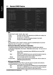
... one of three methods: Auto Allows BIOS to automatically detect IDE/SATA devices during POST. (Default value) None Select this option for automatic device detection. GA-K8N51PVM9-RH-NV Motherboard - 32 - You can use one of the two methods: Auto Allows BIOS to automatically detect IDE/SATA devices during POST(default) None Select this...
... one of three methods: Auto Allows BIOS to automatically detect IDE/SATA devices during POST. (Default value) None Select this option for automatic device detection. GA-K8N51PVM9-RH-NV Motherboard - 32 - You can use one of the two methods: Auto Allows BIOS to automatically detect IDE/SATA devices during POST(default) None Select this...

User Manual
Page 34
... device priority by Floppy. Disabled Disable this menu. Note that there will not be any warning message if the drive installed is 360K. (Default value) GA-K8N51PVM9-RH-NV Motherboard - 34 - Disabled BIOS will determine the floppy disk drive installed is 40 or 80 tracks. 360K type is 40 or 80 tracks. Press to...
... device priority by Floppy. Disabled Disable this menu. Note that there will not be any warning message if the drive installed is 360K. (Default value) GA-K8N51PVM9-RH-NV Motherboard - 34 - Disabled BIOS will determine the floppy disk drive installed is 40 or 80 tracks. 360K type is 40 or 80 tracks. Press to...

User Manual
Page 36
...: Fail-Safe Defaults ESC: Exit F1: General Help F7: Optimized Defaults SATA-II RAID function Enabled Enable SATAII RAID function. Disable this function. (Default value) GA-K8N51PVM9-RH-NV Motherboard - 36 -
...: Fail-Safe Defaults ESC: Exit F1: General Help F7: Optimized Defaults SATA-II RAID function Enabled Enable SATAII RAID function. Disable this function. (Default value) GA-K8N51PVM9-RH-NV Motherboard - 36 -

User Manual
Page 38
... is 3E8/IRQ4. 2E8/IRQ3 Disabled Enable onboard Serial port 1 and address is 2F8/IRQ3. ECP+EPP Using Parallel port as ECP and EPP mode. GA-K8N51PVM9-RH-NV Motherboard - 38 -
... is 3E8/IRQ4. 2E8/IRQ3 Disabled Enable onboard Serial port 1 and address is 2F8/IRQ3. ECP+EPP Using Parallel port as ECP and EPP mode. GA-K8N51PVM9-RH-NV Motherboard - 38 -

User Manual
Page 40
... the system, the system will return to the Last state before AC-power off. Enter Input password (from 1 to 5 characters to set the password here. GA-K8N51PVM9-RH-NV Motherboard - 40 - Any KEY Press any keys on your keyboard have "POWER Key" button, you can press the key to power on the system. Full...
... the system, the system will return to the Last state before AC-power off. Enter Input password (from 1 to 5 characters to set the password here. GA-K8N51PVM9-RH-NV Motherboard - 40 - Any KEY Press any keys on your keyboard have "POWER Key" button, you can press the key to power on the system. Full...

User Manual
Page 42
... case open status [Enabled] Clear case open status at next boot. System/CPU Temperature Detect system/CPU temperature automatically. Monitor CPU temperature at 90oC / 194oF. GA-K8N51PVM9-RH-NV Motherboard - 42 - Monitor CPU temperature at 80oC / 176oF. If you want to reset Case Opened value, enable Reset Case Open Status and save the change...
... case open status [Enabled] Clear case open status at next boot. System/CPU Temperature Detect system/CPU temperature automatically. Monitor CPU temperature at 90oC / 194oF. GA-K8N51PVM9-RH-NV Motherboard - 42 - Monitor CPU temperature at 80oC / 176oF. If you want to reset Case Opened value, enable Reset Case Open Status and save the change...

User Manual
Page 44
... 200.0~300.0MHz Set CPU Frequency from 100MHz to 300MHz. The option will display "Locked" and read only or will automatically assign by CPU detection. GA-K8N51PVM9-RH-NV Motherboard - 44 - PCIE Clock 100~145MHz Set PCIe Clock from 200MHz to 145MHz. K8 CPU Clock Ratio This setup option will not show up if...
... 200.0~300.0MHz Set CPU Frequency from 100MHz to 300MHz. The option will display "Locked" and read only or will automatically assign by CPU detection. GA-K8N51PVM9-RH-NV Motherboard - 44 - PCIE Clock 100~145MHz Set PCIe Clock from 200MHz to 145MHz. K8 CPU Clock Ratio This setup option will not show up if...