
User Manual
Page 1
GA-K8N51GMF/ GA-K8N51GMF-RH AMD Socket 754 Processor Motherboard User's Manual Rev. 1004 12ME-N51GMF-1004R * The WEEE marking on the product indicates this product must not be disposed of with user's other household waste and must be handed over to a designated collection point for the recycling of waste electrical and electronic equipment!! * The WEEE marking applies only in European Union's member states.
GA-K8N51GMF/ GA-K8N51GMF-RH AMD Socket 754 Processor Motherboard User's Manual Rev. 1004 12ME-N51GMF-1004R * The WEEE marking on the product indicates this product must not be disposed of with user's other household waste and must be handed over to a designated collection point for the recycling of waste electrical and electronic equipment!! * The WEEE marking applies only in European Union's member states.

User Manual
Page 2
Motherboard GA-K8N51GMF / GA-K8N51GMF-RH Oct. 26, 2005 Motherboard GA-K8N51GMF GA-K8N51GMF-RH Oct. 26, 2005
Motherboard GA-K8N51GMF / GA-K8N51GMF-RH Oct. 26, 2005 Motherboard GA-K8N51GMF GA-K8N51GMF-RH Oct. 26, 2005
User Manual
Page 4
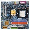
Table of Contents ItemChecklist ...6 OptionalAccessories ...6 GA-K8N51GMF/GA-K8N51GMF-RH Motherboard Layout 7 Block Diagram ...8 Chapter 1 Hardware Installation 9 1-1 Considerations Prior to Installation 9 1-2 Feature Summary 10 1-3 Installation of the CPU and Heatsink 12 1-3-1 Installation of the CPU 12 1-3-2 ...
Table of Contents ItemChecklist ...6 OptionalAccessories ...6 GA-K8N51GMF/GA-K8N51GMF-RH Motherboard Layout 7 Block Diagram ...8 Chapter 1 Hardware Installation 9 1-1 Considerations Prior to Installation 9 1-2 Feature Summary 10 1-3 Installation of the CPU and Heatsink 12 1-3-1 Installation of the CPU 12 1-3-2 ...
User Manual
Page 9
... Chapter 1 Hardware Installation 1-1 Considerations Prior to Installation Preparing Your Computer The motherboard contains numerous delicate electronic circuits and components which can lead to damage to system components as well as physical harm to be an unofficial Gigabyte product. - 9 - Prior to use exceeding the permitted parameters. 6. Instances of violating the conditions recommended in...
... Chapter 1 Hardware Installation 1-1 Considerations Prior to Installation Preparing Your Computer The motherboard contains numerous delicate electronic circuits and components which can lead to damage to system components as well as physical harm to be an unofficial Gigabyte product. - 9 - Prior to use exceeding the permitted parameters. 6. Instances of violating the conditions recommended in...

User Manual
Page 10
...; 1 front audio connector Š 1 CD In connector Š 2 USB 2.0/1.1 connectors for additional 4 USB 2.0/1.1 ports by cable Š 1 SPDIF In/Out connector Š 1 power LED connector GA-K8N51GMF(-RH) Motherboard - 10 -
...; 1 front audio connector Š 1 CD In connector Š 2 USB 2.0/1.1 connectors for additional 4 USB 2.0/1.1 ports by cable Š 1 SPDIF In/Out connector Š 1 power LED connector GA-K8N51GMF(-RH) Motherboard - 10 -

User Manual
Page 11
Hardware Installation For more detailed information please check at the FAQ section on GIGABYTE's website. (Note 2) EasyTune 5 functions may vary depending on the CPU you install. English Rear Panel I/O Š 1 PS/2 keyboard port Š 1 PS/2 mouse port Š 1 parallel ...) Form Factor Š Micro ATX form factor; 24.4cm x 22.0cm (Note 1) Whether the CPU Smart FAN Control function is supported will depend on different motherboards. - 11 -
Hardware Installation For more detailed information please check at the FAQ section on GIGABYTE's website. (Note 2) EasyTune 5 functions may vary depending on the CPU you install. English Rear Panel I/O Š 1 PS/2 keyboard port Š 1 PS/2 mouse port Š 1 parallel ...) Form Factor Š Micro ATX form factor; 24.4cm x 22.0cm (Note 1) Whether the CPU Smart FAN Control function is supported will depend on different motherboards. - 11 -
User Manual
Page 12
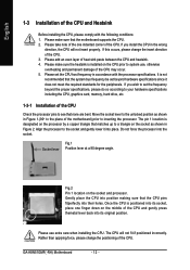
...themetal lever back into place. Once the CPU is installed on the socket as shown in Figure 1.(90o to the plane of the motherboard) prior to the unlocked position as shown in accordance with the following conditions: 1. If this occurs, please change the positioning of... inserting the processor. If you wish to set the CPU host frequency in Figure 2. Do not force the processor into their holes. GA-K8N51GMF(-RH) Motherboard - 12 - English 1-3 Installation of the CPU and Heatsink Before installing the CPU, please comply with the processor specifications. Rather than ...
...themetal lever back into place. Once the CPU is installed on the socket as shown in Figure 1.(90o to the plane of the motherboard) prior to the unlocked position as shown in accordance with the following conditions: 1. If this occurs, please change the positioning of... inserting the processor. If you wish to set the CPU host frequency in Figure 2. Do not force the processor into their holes. GA-K8N51GMF(-RH) Motherboard - 12 - English 1-3 Installation of the CPU and Heatsink Before installing the CPU, please comply with the processor specifications. Rather than ...
User Manual
Page 13
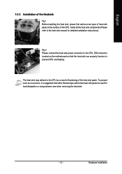
... sink paste. English 1-3-2 Installation of the Heatsink Fig.1 Before installing the heat sink, please first add an even layer of heat sink paste on the motherboard so that either thermal tape rather than heat sink paste be used for detailed installation instructions). Fig.2 Please connect the heat sink power connector to...
... sink paste. English 1-3-2 Installation of the Heatsink Fig.1 Before installing the heat sink, please first add an even layer of heat sink paste on the motherboard so that either thermal tape rather than heat sink paste be used for detailed installation instructions). Fig.2 Please connect the heat sink power connector to...

User Manual
Page 14
...modules, please make sure that memory of similar capacity, specifications and brand be used. 2. Then push it down. GA-K8N51GMF(-RH) Motherboard - 14 - The motherboard supports DDR memory modules, whereby BIOS will automatically detect memory capacity and specifications. Fig.2 Close the plastic clip at ... Installation of Memory Before installing the memory modules, please comply with each slot. The memory capacity used is supported by the motherboard. It is switched off to insert the module, please switch the direction. Insert the DIMM memory module vertically into the DIMM ...
...modules, please make sure that memory of similar capacity, specifications and brand be used. 2. Then push it down. GA-K8N51GMF(-RH) Motherboard - 14 - The motherboard supports DDR memory modules, whereby BIOS will automatically detect memory capacity and specifications. Fig.2 Close the plastic clip at ... Installation of Memory Before installing the memory modules, please comply with each slot. The memory capacity used is supported by the motherboard. It is switched off to insert the module, please switch the direction. Insert the DIMM memory module vertically into the DIMM ...
User Manual
Page 15
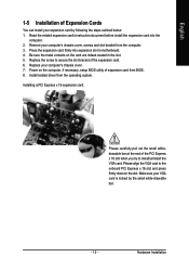
... PCI Express x 16 slot when you try to the onboard PCI Express x 16 slot and press firmly down on the card are indeed seated in motherboard. 4. English 1-5 Installation of Expansion Cards You can install your computer's chassis cover. 7. Press the expansion card firmly into the computer. 2.
... PCI Express x 16 slot when you try to the onboard PCI Express x 16 slot and press firmly down on the card are indeed seated in motherboard. 4. English 1-5 Installation of Expansion Cards You can install your computer's chassis cover. 7. Press the expansion card firmly into the computer. 2.

User Manual
Page 16
... connected to Line In jack. Also make sure your OS does not support USB controller, please contact OS vendor for possible patch or driver upgrade. GA-K8N51GMF(-RH) Motherboard - 16 - Parallel Port The parallel port allows connection of 10/100Mbps. Be careful with the polarity of Electrical and Electronics Engineers, which has features...
... connected to Line In jack. Also make sure your OS does not support USB controller, please contact OS vendor for possible patch or driver upgrade. GA-K8N51GMF(-RH) Motherboard - 16 - Parallel Port The parallel port allows connection of 10/100Mbps. Be careful with the polarity of Electrical and Electronics Engineers, which has features...

User Manual
Page 18
...18 - The ATX_12V power connector mainly supplies power to handle the system voltage requirements. Align the power connector with its proper location on the motherboard before plugging in the power cord ; Please use a power supply that is able to the CPU. English 1/2) ATX_12V / ATX (Power ...cover on the power connector on the motherboard and connect tightly. If a power supply is not connected, the system will not start . Otherwise, please do not remove it. 42 31 Pin No. 1 2 3 4 Definition GND GND +12V +12V GA-K8N51GMF(-RH) Motherboard Pin No. Before connecting the power ...
...18 - The ATX_12V power connector mainly supplies power to handle the system voltage requirements. Align the power connector with its proper location on the motherboard before plugging in the power cord ; Please use a power supply that is able to the CPU. English 1/2) ATX_12V / ATX (Power ...cover on the power connector on the motherboard and connect tightly. If a power supply is not connected, the system will not start . Otherwise, please do not remove it. 42 31 Pin No. 1 2 3 4 Definition GND GND +12V +12V GA-K8N51GMF(-RH) Motherboard Pin No. Before connecting the power ...
User Manual
Page 20
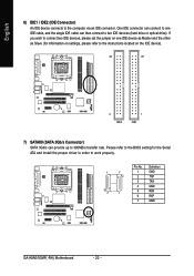
... an IDE connector. English 6) IDE1 / IDE2 (IDE Connector) An IDE device connects to work properly. 1 7 7 1 Pin No. 1 2 3 4 5 6 7 Definition GND TXP TXN GND RXN RXP GND GA-K8N51GMF(-RH) Motherboard - 20 -
... an IDE connector. English 6) IDE1 / IDE2 (IDE Connector) An IDE device connects to work properly. 1 7 7 1 Pin No. 1 2 3 4 5 6 7 Definition GND TXP TXN GND RXN RXP GND GA-K8N51GMF(-RH) Motherboard - 20 -
User Manual
Page 22
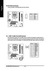
... contact your local dealer. Definition 1 Power (5V) 2 10 2 Power (5V) 3 USB DX- 1 9 4 USB Dy- 5 USB DX+ 6 USB Dy+ 7 GND 8 GND 9 No Pin 10 NC GA-K8N51GMF(-RH) Motherboard - 22 - Check the pin assignment carefully while you connect the front USB cable, incorrect connection between the cable and connector will make the device unable...
... contact your local dealer. Definition 1 Power (5V) 2 10 2 Power (5V) 3 USB DX- 1 9 4 USB Dy- 5 USB DX+ 6 USB Dy+ 7 GND 8 GND 9 No Pin 10 NC GA-K8N51GMF(-RH) Motherboard - 22 - Check the pin assignment carefully while you connect the front USB cable, incorrect connection between the cable and connector will make the device unable...

User Manual
Page 24
Replace only with the same or equivalent type recommended by this jumper. 1 Open: Normal 1 Short: Clear CMOS 15) BATTERY GA-K8N51GMF(-RH) Motherboard Danger of used batteries according to the manufacturer's instructions. English 14) CLR_CMOS (Clear CMOS) You may clear the CMOS data to its default values by ...
Replace only with the same or equivalent type recommended by this jumper. 1 Open: Normal 1 Short: Clear CMOS 15) BATTERY GA-K8N51GMF(-RH) Motherboard Danger of used batteries according to the manufacturer's instructions. English 14) CLR_CMOS (Clear CMOS) You may clear the CMOS data to its default values by ...

User Manual
Page 27
... to quickly and easily update or backup BIOS without entering the operating system. @BIOS is turned off, the battery on the motherboard supplies the necessary power to a new BIOS, either GIGABYTE's Q-Flash or @BIOS utility can enter the BIOS setup screen by pressing "Ctrl + F1". Quit and not save the ...caution and avoid inadequate operation that may result in the CMOS SRAM of the screen. When the power is displayed at the bottom of the motherboard. Status Page Setup Menu / Option Page Setup Menu Press to pop up BIOS for Status Page Setup Menu and Option Page Setup Menu ...
... to quickly and easily update or backup BIOS without entering the operating system. @BIOS is turned off, the battery on the motherboard supplies the necessary power to a new BIOS, either GIGABYTE's Q-Flash or @BIOS utility can enter the BIOS setup screen by pressing "Ctrl + F1". Quit and not save the ...caution and avoid inadequate operation that may result in the CMOS SRAM of the screen. When the power is displayed at the bottom of the motherboard. Status Page Setup Menu / Option Page Setup Menu Press to pop up BIOS for Status Page Setup Menu and Option Page Setup Menu ...

User Manual
Page 28
GA-K8N51GMF-RH F4 . . . . :BIOS Setup/Q-Flash, : Xpress Recovery2, For Boot Menu 01/16/2006-... the system reset to exit this chapter are for reference only and may differ from the exact settings for your motherboard. CMOS Setup Utility-Copyright (C) 1984-2005 Award Software ` Standard CMOS Features ` Advanced BIOS Features ` Integrated Peripherals...00PG, An Energy Star Ally Copyright (C) 1984-2005, Award Software, Inc. Press to the default for stability. GA-K8N51GMF(-RH) Motherboard - 28 - If you can't find the setting you enter Award BIOS CMOS Setup Utility, the Main Menu (...
GA-K8N51GMF-RH F4 . . . . :BIOS Setup/Q-Flash, : Xpress Recovery2, For Boot Menu 01/16/2006-... the system reset to exit this chapter are for reference only and may differ from the exact settings for your motherboard. CMOS Setup Utility-Copyright (C) 1984-2005 Award Software ` Standard CMOS Features ` Advanced BIOS Features ` Integrated Peripherals...00PG, An Energy Star Ally Copyright (C) 1984-2005, Award Software, Inc. Press to the default for stability. GA-K8N51GMF(-RH) Motherboard - 28 - If you can't find the setting you enter Award BIOS CMOS Setup Utility, the Main Menu (...
User Manual
Page 30
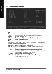
... the month) 1999 to automatically detect IDE devices during POST(default) None Select this if no IDE devices are : CHS/LBA/Large/Auto(default:Auto) GA-K8N51GMF(-RH) Motherboard - 30 - IDE Channel 0 Master, Slave, IDE Channel 1 Master, Slave IDE HDD Auto-Detection Press "Enter" to select this to Sat. The time is display...
... the month) 1999 to automatically detect IDE devices during POST(default) None Select this if no IDE devices are : CHS/LBA/Large/Auto(default:Auto) GA-K8N51GMF(-RH) Motherboard - 30 - IDE Channel 0 Master, Slave, IDE Channel 1 Master, Slave IDE HDD Auto-Detection Press "Enter" to select this to Sat. The time is display...
User Manual
Page 32
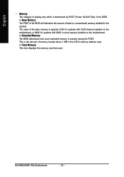
... amount of the BIOS. Total Memory This item displays the memory size that used. The value of the base memory is present during the POST. GA-K8N51GMF(-RH) Motherboard - 32 - English Memory The category is display-only which is the amount of memory located above 1 MB in the system. This is determined by...
... amount of the BIOS. Total Memory This item displays the memory size that used. The value of the base memory is present during the POST. GA-K8N51GMF(-RH) Motherboard - 32 - English Memory The category is display-only which is the amount of memory located above 1 MB in the system. This is determined by...
User Manual
Page 34
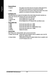
...the prompt. Onboard VGA Set Init Display First to select the first initiation of the monitor display from which card when you to onboard VGA. GA-K8N51GMF(-RH) Motherboard - 34 - Enable If No Ext PEG Onboard GPU will be disabled if there is a graphics card on the PCI Express slot. (Default... value) Always Enable Onboard GPU will always be enabled whether there is a graphics card on the motherboard. PCI Slot Set Init Display First to 32MB. PEG Set Init Display First to PCI Express VGA card.(Default value) Frame Buffer Size 16MB ...
...the prompt. Onboard VGA Set Init Display First to select the first initiation of the monitor display from which card when you to onboard VGA. GA-K8N51GMF(-RH) Motherboard - 34 - Enable If No Ext PEG Onboard GPU will be disabled if there is a graphics card on the PCI Express slot. (Default... value) Always Enable Onboard GPU will always be enabled whether there is a graphics card on the motherboard. PCI Slot Set Init Display First to 32MB. PEG Set Init Display First to PCI Express VGA card.(Default value) Frame Buffer Size 16MB ...


