User Manual
Page 7
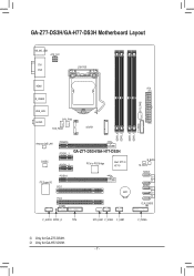
k Only for GA-Z77-DS3H. GA-Z77-DS3H/GA-H77-DS3H Motherboard Layout KB_MS_USB ATX_12V DVI VGA LGA1155 HDMI ATX R_USB30 SYS_FAN2 USB_LAN AUDIO CPU_FAN SYS_FAN3 mSATA DDR3_4 DDR3_2 DDR3_3 DDR3_1 F_USB30 Atheros GbE LAN CODEC PCIEX16 PCIEX1_1 GA-Z77-DS3H/GA-H77-DS3H PCIEX1_2 PCIe to PCI Bridge Intel® Z77j/ H77k PCIEX4 iTE Super I/O PCI1 BAT PCI2 COMA B_BIOS M_BIOS SATA3 0 1 SATA2 2 3 4 CLR_CMOS F_AUDIO SPDIF_O TPM SYS_FAN1 F_USB2 F_USB1 F_PANEL j Only for GA-H77-DS3H. - 7 -
k Only for GA-Z77-DS3H. GA-Z77-DS3H/GA-H77-DS3H Motherboard Layout KB_MS_USB ATX_12V DVI VGA LGA1155 HDMI ATX R_USB30 SYS_FAN2 USB_LAN AUDIO CPU_FAN SYS_FAN3 mSATA DDR3_4 DDR3_2 DDR3_3 DDR3_1 F_USB30 Atheros GbE LAN CODEC PCIEX16 PCIEX1_1 GA-Z77-DS3H/GA-H77-DS3H PCIEX1_2 PCIe to PCI Bridge Intel® Z77j/ H77k PCIEX4 iTE Super I/O PCI1 BAT PCI2 COMA B_BIOS M_BIOS SATA3 0 1 SATA2 2 3 4 CLR_CMOS F_AUDIO SPDIF_O TPM SYS_FAN1 F_USB2 F_USB1 F_PANEL j Only for GA-H77-DS3H. - 7 -
User Manual
Page 21
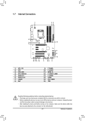
1-7 Internal Connectors 1 42 4 3 13 7 5 6 15 10 11 14 16 4 12 8 9 1) ATX_12V 2) ATX 3) CPU_FAN 4) SYS_FAN1/2/3 5) SATA3 0/1 6) SATA2 2/3/4 7) mSATA 8) BAT 9) F_PANEL 10) F_AUDIO 11) SPDIF_O 12) F_USB1/F_USB2 13) F_USB30 14) COMA 15) CLR_CMOS 16) TPM Read the following guidelines before turning on the motherboard. - 21 - Hardware Installation Unplug the power cord from the power...
1-7 Internal Connectors 1 42 4 3 13 7 5 6 15 10 11 14 16 4 12 8 9 1) ATX_12V 2) ATX 3) CPU_FAN 4) SYS_FAN1/2/3 5) SATA3 0/1 6) SATA2 2/3/4 7) mSATA 8) BAT 9) F_PANEL 10) F_AUDIO 11) SPDIF_O 12) F_USB1/F_USB2 13) F_USB30 14) COMA 15) CLR_CMOS 16) TPM Read the following guidelines before turning on the motherboard. - 21 - Hardware Installation Unplug the power cord from the power...
User Manual
Page 22
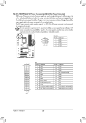
...greater). 1/2) ATX_12V/ATX (2x2 12V Power Connector and 2x12 Main Power Connector) With the use of the power connector, the power supply can supply enough stable power to all devices are properly installed. If a power supply is turned off and all the components on the motherboard. Connect the power... be used that can lead to an unstable or unbootable system. 3 4 1 2 ATX_12V ATX_12V: Pin No. 1 2 3 4 Definition GND GND +12V +12V 12 24 1 13 ATX ATX: Pin No. 1 2 3 4 5 6 7 8 9 10 11 12 Definition Pin No. 3.3V 13 3.3V 14 GND 15 +5V 16 GND 17 +5V 18 GND 19 ...
...greater). 1/2) ATX_12V/ATX (2x2 12V Power Connector and 2x12 Main Power Connector) With the use of the power connector, the power supply can supply enough stable power to all devices are properly installed. If a power supply is turned off and all the components on the motherboard. Connect the power... be used that can lead to an unstable or unbootable system. 3 4 1 2 ATX_12V ATX_12V: Pin No. 1 2 3 4 Definition GND GND +12V +12V 12 24 1 13 ATX ATX: Pin No. 1 2 3 4 5 6 7 8 9 10 11 12 Definition Pin No. 3.3V 13 3.3V 14 GND 15 +5V 16 GND 17 +5V 18 GND 19 ...

User Manual
Page 93
...Yes The problem is installed properly on the memory slot. Secure the CPU cooler No on the power to the motherboard. Check if the memory is verified and solved. Connect the ATX main power cable and the 12V power cable. Turn on the CPU. No Check if the CPU cooler is ...all peripherals, connecting cables, and power cord etc. Is the power connector of the CPU cooler connected to solve the problem. Make sure the motherboard does not short-circuit with the chassis or other metal objects. START Turn off the power. The problem is securely seated in the expansion slot...
...Yes The problem is installed properly on the memory slot. Secure the CPU cooler No on the power to the motherboard. Check if the memory is verified and solved. Connect the ATX main power cable and the 12V power cable. Turn on the CPU. No Check if the CPU cooler is ...all peripherals, connecting cables, and power cord etc. Is the power connector of the CPU cooler connected to solve the problem. Make sure the motherboard does not short-circuit with the chassis or other metal objects. START Turn off the power. The problem is securely seated in the expansion slot...


