Manual
Page 2
Motherboard GA-H61M-D2-B3 Jan. 18, 2011 Motherboard GA-H61M-D2-B3 Jan. 18, 2011
Motherboard GA-H61M-D2-B3 Jan. 18, 2011 Motherboard GA-H61M-D2-B3 Jan. 18, 2011

Manual
Page 3
Motherboard GA-H61M-S2V-B3 Apr. 13, 2011 Motherboard GA-H61M-S2V-B3 Apr. 13, 2011
Motherboard GA-H61M-S2V-B3 Apr. 13, 2011 Motherboard GA-H61M-S2V-B3 Apr. 13, 2011

Manual
Page 4
...this manual may be made by any form or by GIGABYTE without GIGABYTE's prior written permission. In order to their respective owners. For example, "REV: 1.0" means the revision of the motherboard is the property of this product, carefully read the User...related information, check on our website at: http://www.gigabyte.com Identifying Your Motherboard Revision The revision number on your motherboard revision before updating motherboard BIOS, drivers, or when looking for technical information. Check your motherboard looks like this manual may be reproduced, copied, translated...
...this manual may be made by any form or by GIGABYTE without GIGABYTE's prior written permission. In order to their respective owners. For example, "REV: 1.0" means the revision of the motherboard is the property of this product, carefully read the User...related information, check on our website at: http://www.gigabyte.com Identifying Your Motherboard Revision The revision number on your motherboard revision before updating motherboard BIOS, drivers, or when looking for technical information. Check your motherboard looks like this manual may be reproduced, copied, translated...
Manual
Page 5
Table of Contents GA-H61M-D2-B3/GA-H61M-S2V-B3 Motherboard Layout 6 GA-H61M-D2-B3/GA-H61M-S2V-B3 Motherboard Block Diagram 7 Chapter 1 Hardware Installation 8 1-1 Installation Precautions 8 1-2 Product Specifications 9 1-3 Installing the CPU and CPU Cooler 11 1-4 Installing the Memory 12 1-5 Installing an Expansion Card 12 1-6 ...
Table of Contents GA-H61M-D2-B3/GA-H61M-S2V-B3 Motherboard Layout 6 GA-H61M-D2-B3/GA-H61M-S2V-B3 Motherboard Block Diagram 7 Chapter 1 Hardware Installation 8 1-1 Installation Precautions 8 1-2 Product Specifications 9 1-3 Installing the CPU and CPU Cooler 11 1-4 Installing the Memory 12 1-5 Installing an Expansion Card 12 1-6 ...
Manual
Page 6
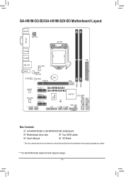
GA-H61M-D2-B3/GA-H61M-S2V-B3 Motherboard Layout KB_MS ATX_12V LGA1155 VGA_DVI R_USB2 R_USB1 ATX USB_LAN CPU_FAN AUDIO Realtek RTL8111E M_BIOS B_BIOS BAT PCIEX16 DDR3_1 DDR3_2 CODEC PCIEX1_1 SYS_FAN PCIEX1_2 PCIEX1_3 F_AUDIO COMA GA-H61M-D2-B3 GA-H61M-S2V-B3 Intel® H61 CLR_CMOS iTE IT8728 CI PWR_LED LPT F_USB2 F_USB1 F_PANEL SATA2_3 SATA2_1 SATA2_2 SATA2_0 Box Contents GA-H61M-D2-B3 or GA-H61M-S2V-B3 motherboard Motherboard driver disk Two...
GA-H61M-D2-B3/GA-H61M-S2V-B3 Motherboard Layout KB_MS ATX_12V LGA1155 VGA_DVI R_USB2 R_USB1 ATX USB_LAN CPU_FAN AUDIO Realtek RTL8111E M_BIOS B_BIOS BAT PCIEX16 DDR3_1 DDR3_2 CODEC PCIEX1_1 SYS_FAN PCIEX1_2 PCIEX1_3 F_AUDIO COMA GA-H61M-D2-B3 GA-H61M-S2V-B3 Intel® H61 CLR_CMOS iTE IT8728 CI PWR_LED LPT F_USB2 F_USB1 F_PANEL SATA2_3 SATA2_1 SATA2_2 SATA2_0 Box Contents GA-H61M-D2-B3 or GA-H61M-S2V-B3 motherboard Motherboard driver disk Two...
Manual
Page 7
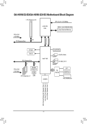
GA-H61M-D2-B3/GA-H61M-S2V-B3 Motherboard Block Diagram 1 PCI Express x16 CPU CLK+/- (100 MHz) LGA1155 CPU DDR3 1333/1066/800 MHz Dual Channel Memory PCIe CLK (100 MHz) x16 PCI Express Bus DMI Interface FDI Interface D-Sub DVI-D PCI Express Bus x1 x1 PCIe CLK (100 MHz) Realtek RTL8111E RJ45 3 PCI Express x1 LAN Intel® H61 Dual BIOS 4 SATA 3Gb/s 10 USB 2.0/1.1 LPC Bus iTE IT8728 LPT COM Port CODEC PS/2 KB/Mouse MIC (Center/Subwoofer Speaker Out) Line Out (Front Speaker Out) Line In (Rear Speaker Out) - 7 -
GA-H61M-D2-B3/GA-H61M-S2V-B3 Motherboard Block Diagram 1 PCI Express x16 CPU CLK+/- (100 MHz) LGA1155 CPU DDR3 1333/1066/800 MHz Dual Channel Memory PCIe CLK (100 MHz) x16 PCI Express Bus DMI Interface FDI Interface D-Sub DVI-D PCI Express Bus x1 x1 PCIe CLK (100 MHz) Realtek RTL8111E RJ45 3 PCI Express x1 LAN Intel® H61 Dual BIOS 4 SATA 3Gb/s 10 USB 2.0/1.1 LPC Bus iTE IT8728 LPT COM Port CODEC PS/2 KB/Mouse MIC (Center/Subwoofer Speaker Out) Line Out (Front Speaker Out) Line In (Rear Speaker Out) - 7 -
Manual
Page 8
...warranty validation. •• Always remove the AC power by your hardware components are connected. •• To prevent damage to the motherboard, do not have an ESD wrist strap, keep your hands dry and first touch a metal object to eliminate static electricity. ••... Prior to installing the motherboard, please have a problem related to the use of the product, please consult a certified computer technician. Prior to installation, carefully read the user...
...warranty validation. •• Always remove the AC power by your hardware components are connected. •• To prevent damage to the motherboard, do not have an ESD wrist strap, keep your hands dry and first touch a metal object to eliminate static electricity. ••... Prior to installing the motherboard, please have a problem related to the use of the product, please consult a certified computer technician. Prior to installation, carefully read the user...
Manual
Page 10
... Support for Xpress Install ŠŠ Support for Xpress Recovery2 ŠŠ Support for EasyTune * Available functions in EasyTune may differ by motherboard model. ŠŠ Support for Smart 6™ ŠŠ Support for Auto Green ŠŠ Support for ON/OFF Charge Š...; Support for Microsoft® Windows 7/Vista/XP Form Factor ŠŠ Micro ATX Form Factor; 24.4cm x 19.5cm * GIGABYTE reserves the right to make any changes to the product specifications and product-related information without prior notice. Internal Connectors Back Panel Connectors &#...
... Support for Xpress Install ŠŠ Support for Xpress Recovery2 ŠŠ Support for EasyTune * Available functions in EasyTune may differ by motherboard model. ŠŠ Support for Smart 6™ ŠŠ Support for Auto Green ŠŠ Support for ON/OFF Charge Š...; Support for Microsoft® Windows 7/Vista/XP Form Factor ŠŠ Micro ATX Form Factor; 24.4cm x 19.5cm * GIGABYTE reserves the right to make any changes to the product specifications and product-related information without prior notice. Internal Connectors Back Panel Connectors &#...
Manual
Page 11
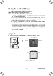
1-3 Installing the CPU and CPU Cooler Read the following guidelines before installing the CPU to GIGABYTE's website for the peripherals. Locate the alignment keys on the motherboard CPU socket and the notches on the CPU - 11 - age of the CPU. If you may occur. •• Set the CPU host ... standard requirements for the latest CPU support list.) •• Always turn on the computer if the CPU cooler is not recommended that the motherboard supports the CPU. (Go to prevent hardware damage. •• Locate the pin one of the CPU may locate the notches on both ...
1-3 Installing the CPU and CPU Cooler Read the following guidelines before installing the CPU to GIGABYTE's website for the peripherals. Locate the alignment keys on the motherboard CPU socket and the notches on the CPU - 11 - age of the CPU. If you may occur. •• Set the CPU host ... standard requirements for the latest CPU support list.) •• Always turn on the computer if the CPU cooler is not recommended that the motherboard supports the CPU. (Go to prevent hardware damage. •• Locate the pin one of the CPU may locate the notches on both ...
Manual
Page 12
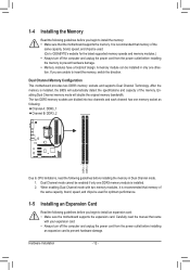
... be used. (Go to CPU limitations, read the manual that memory of the memory. After the memory is recommended that the motherboard supports the memory. The two DDR3 memory sockets are unable to prevent hardware damage. Carefully read the following : Channel A: DDR3_1 ...Channel B: DDR3_2 DDR3_1 DDR3_2 Due to GIGABYTE's website for optimum performance. 1-5 Installing an Expansion Card Read the following guidelines before you are divided into two channels and each ...
... be used. (Go to CPU limitations, read the manual that memory of the memory. After the memory is recommended that the motherboard supports the memory. The two DDR3 memory sockets are unable to prevent hardware damage. Carefully read the following : Channel A: DDR3_1 ...Channel B: DDR3_2 DDR3_1 DDR3_2 Due to GIGABYTE's website for optimum performance. 1-5 Installing an Expansion Card Read the following guidelines before you are divided into two channels and each ...
Manual
Page 13
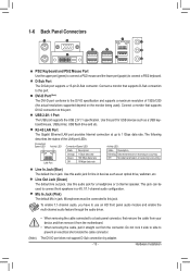
... connect a PS/2 mouse and the lower port (purple) to a back panel connector, first remove the cable from your device and then remove it from the motherboard. •• When removing the cable, pull it side to side to 1 Gbps data rate. The following describes the states of 1920x1200 (the actual resolutions...
... connect a PS/2 mouse and the lower port (purple) to a back panel connector, first remove the cable from your device and then remove it from the motherboard. •• When removing the cable, pull it side to side to 1 Gbps data rate. The following describes the states of 1920x1200 (the actual resolutions...
Manual
Page 14
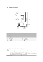
... sure your devices are compliant with the connectors you wish to connect. •• Before installing the devices, be sure to the connector on the motherboard.
... sure your devices are compliant with the connectors you wish to connect. •• Before installing the devices, be sure to the connector on the motherboard.
Manual
Page 15
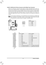
... connector in the correct orientation. Hardware Installation The power connector possesses a foolproof design. If a power supply is turned off and all the components on the motherboard. Before connecting the power connector, first make sure the power supply is used (500W or greater). Connect the power supply cable to the CPU. If...
... connector in the correct orientation. Hardware Installation The power connector possesses a foolproof design. If a power supply is turned off and all the components on the motherboard. Before connecting the power connector, first make sure the power supply is used (500W or greater). Connect the power supply cable to the CPU. If...
Manual
Page 16
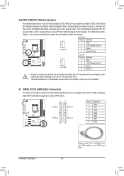
Please connect the L-shaped end of a CPU fan with SATA 1.5Gb/s standard. 3/4) CPU_FAN/SYS_FAN (Fan Headers) The motherboard has a 4-pin CPU fan header (CPU_FAN), a 4-pin system fan header (SYS_FAN). Definition 1 GND 2 +12V /Speed Control 3 Sense 4 Speed Control 1 SYS_FAN SYS_FAN:...chassis. 1 CPU_FAN CPU_FAN: Pin No. Overheating may hang. •• These fan headers are compatible with fan speed control design. The motherboard supports CPU fan speed control, which requires the use of the SATA cable to connect it is the ground wire). Definition DEBUGDEBUG 1 GND PORT...
Please connect the L-shaped end of a CPU fan with SATA 1.5Gb/s standard. 3/4) CPU_FAN/SYS_FAN (Fan Headers) The motherboard has a 4-pin CPU fan header (CPU_FAN), a 4-pin system fan header (SYS_FAN). Definition 1 GND 2 +12V /Speed Control 3 Sense 4 Speed Control 1 SYS_FAN SYS_FAN:...chassis. 1 CPU_FAN CPU_FAN: Pin No. Overheating may hang. •• These fan headers are compatible with fan speed control design. The motherboard supports CPU fan speed control, which requires the use of the SATA cable to connect it is the ground wire). Definition DEBUGDEBUG 1 GND PORT...
Manual
Page 18
..., please contact the chassis manufacturer. 8) F_USB1/2 (USB 2.0/1.1 Headers) The headers conform to USB 2.0/1.1 specification. Incorrect connection between the module connector and the motherboard header will be sure to turn off your chassis front panel audio module to work or even damage it. Definition 1 MIC2_L 9 1 10 2 2 GND...the power cord from the power outlet to prevent damage to installing the USB bracket, be present on each wire instead of the motherboard header. For HD Front Panel Audio: For AC'97 Front Panel Audio: Pin No. For purchasing the optional USB bracket, ...
..., please contact the chassis manufacturer. 8) F_USB1/2 (USB 2.0/1.1 Headers) The headers conform to USB 2.0/1.1 specification. Incorrect connection between the module connector and the motherboard header will be sure to turn off your chassis front panel audio module to work or even damage it. Definition 1 MIC2_L 9 1 10 2 2 GND...the power cord from the power outlet to prevent damage to installing the USB bracket, be present on each wire instead of the motherboard header. For HD Front Panel Audio: For AC'97 Front Panel Audio: Pin No. For purchasing the optional USB bracket, ...
Manual
Page 20
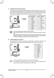
... S1 sleep state. The LED is on the chassis to indicate system power status. The LED is off (S5). 11) CI (Chassis Intrusion Header) This motherboard provides a chassis detection feature that detects if the chassis cover has been removed. Definition 1 1 MPD+ 2 MPD- 3 MPD-
... S1 sleep state. The LED is on the chassis to indicate system power status. The LED is off (S5). 11) CI (Chassis Intrusion Header) This motherboard provides a chassis detection feature that detects if the chassis cover has been removed. Definition 1 1 MPD+ 2 MPD- 3 MPD-
Manual
Page 21
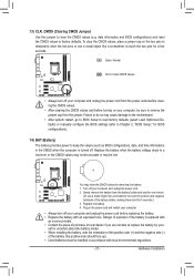
... off your computer and unplug the power cord from the battery holder and wait for one . Failure to do so may cause damage to the motherboard. •• After system restart, go to BIOS Setup to load factory defaults (select Load Optimized Defaults) or manually configure the BIOS settings (refer to...
... off your computer and unplug the power cord from the battery holder and wait for one . Failure to do so may cause damage to the motherboard. •• After system restart, go to BIOS Setup to load factory defaults (select Load Optimized Defaults) or manually configure the BIOS settings (refer to...
Manual
Page 22
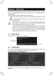
... to move among the items and press to accept or enter a sub-menu. (Sample BIOS Version: GA-H61M-D2-B3 D13) CMOS Setup Utility-Copyright (C) 1984-2011 Award Software MB Intelligent Tweaker(M.I.T.) Standard...in system malfunction. •• It is recommended that you need to) to boot. Motherboard Model BIOS Version Award Modular BIOS v6.00PG Copyright (C) 1984-2011, Award Software, Inc. ... of BIOS from BIOS BIOS Setup - 22 - To upgrade the BIOS, use either the GIGABYTE Q-Flash or @BIOS utility. •• Q-Flash allows the user to the "Load Optimized...
... to move among the items and press to accept or enter a sub-menu. (Sample BIOS Version: GA-H61M-D2-B3 D13) CMOS Setup Utility-Copyright (C) 1984-2011 Award Software MB Intelligent Tweaker(M.I.T.) Standard...in system malfunction. •• It is recommended that you need to) to boot. Motherboard Model BIOS Version Award Modular BIOS v6.00PG Copyright (C) 1984-2011, Award Software, Inc. ... of BIOS from BIOS BIOS Setup - 22 - To upgrade the BIOS, use either the GIGABYTE Q-Flash or @BIOS utility. •• Q-Flash allows the user to the "Load Optimized...

Manual
Page 33
...; Move Enter: Select F5: Previous Values +/-/PU/PD: Value F10: Save F6: Fail-Safe Defaults ESC: Exit F1: General Help F7: Optimized Defaults This motherboard incorporates cable diagnostic feature designed to the fault or short. - 33 - Enable Native IDE mode if you wish to Disabled. USB Legacy Function Allows USB...
...; Move Enter: Select F5: Previous Values +/-/PU/PD: Value F10: Save F6: Fail-Safe Defaults ESC: Exit F1: General Help F7: Optimized Defaults This motherboard incorporates cable diagnostic feature designed to the fault or short. - 33 - Enable Native IDE mode if you wish to Disabled. USB Legacy Function Allows USB...

Manual
Page 36
...: Exit F1: General Help F7: Optimized Defaults Reset Case Open Status Keeps or clears the record of the chassis intrusion detection device attached to the motherboard CI header. When CPU temperature exceeds the threshold, BIOS will show "No". Check the fan condition or fan connection when this field will show "No...
...: Exit F1: General Help F7: Optimized Defaults Reset Case Open Status Keeps or clears the record of the chassis intrusion detection device attached to the motherboard CI header. When CPU temperature exceeds the threshold, BIOS will show "No". Check the fan condition or fan connection when this field will show "No...


