Manual
Page 5
... Chapter 5 Appendix ...83 5-1 Configuring SATA Hard Drive(s 83 5-1-1 Configuring Intel ICH10R SATA Controllers1 83 5-1-2 Configuring GIGABYTE SATA2 SATA Controller 89 5-1-3 Making a SATA RAID/AHCI Driver Diskette 95 5-1-4 Installing the SATA RAID/AHCI Driver and...Configuring 2/4/5.1/7.1-Channel Audio 105 5-2-2 Installing the S/PDIF In Cable (Optional 107 5-2-3 Configuring Microphone Recording 108 5-2-4 Using the Sound Recorder 110 5-3 Troubleshooting 111 5-3-1 Frequently Asked Questions 111 5-3-2 Troubleshooting Procedure 112 5-4 Regulatory Statements 114 1 Only for GA-EP45-UD3R. - ...
... Chapter 5 Appendix ...83 5-1 Configuring SATA Hard Drive(s 83 5-1-1 Configuring Intel ICH10R SATA Controllers1 83 5-1-2 Configuring GIGABYTE SATA2 SATA Controller 89 5-1-3 Making a SATA RAID/AHCI Driver Diskette 95 5-1-4 Installing the SATA RAID/AHCI Driver and...Configuring 2/4/5.1/7.1-Channel Audio 105 5-2-2 Installing the S/PDIF In Cable (Optional 107 5-2-3 Configuring Microphone Recording 108 5-2-4 Using the Sound Recorder 110 5-3 Troubleshooting 111 5-3-1 Frequently Asked Questions 111 5-3-2 Troubleshooting Procedure 112 5-4 Regulatory Statements 114 1 Only for GA-EP45-UD3R. - ...

Manual
Page 7
GA-EP45-UD3R/UD3 DDR2_1 DDR2_2 DDR2_3 DDR2_4 GSATA2_0 GSATA2_1 GA-EP45-UD3R/UD3 Motherboard Layout PWR_FAN KB_MS R_SPDIF ATX_12V_2X4 USB_1394_2 USB_1394_1 R_USB LGA775 CPU_FAN PHASE LED ATX USB_LAN AUDIO F_AUDIO SYS_FAN1 PCIEX1_1 RTL8111C PCIEX16 PCIEX1_2 CODEC PCIEX1_3 BAT SPDIF_O CI PCI1 IT8718 SPDIF_I PCI2 PCI3 CD_IN Intel® P45 IDE SYS_FAN2 GIGABYTE Intel® ICH10R1 SATA2 Intel®...
GA-EP45-UD3R/UD3 DDR2_1 DDR2_2 DDR2_3 DDR2_4 GSATA2_0 GSATA2_1 GA-EP45-UD3R/UD3 Motherboard Layout PWR_FAN KB_MS R_SPDIF ATX_12V_2X4 USB_1394_2 USB_1394_1 R_USB LGA775 CPU_FAN PHASE LED ATX USB_LAN AUDIO F_AUDIO SYS_FAN1 PCIEX1_1 RTL8111C PCIEX16 PCIEX1_2 CODEC PCIEX1_3 BAT SPDIF_O CI PCI1 IT8718 SPDIF_I PCI2 PCI3 CD_IN Intel® P45 IDE SYS_FAN2 GIGABYTE Intel® ICH10R1 SATA2 Intel®...

Manual
Page 10
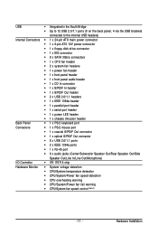
...138; Up to 3 IEEE 1394a ports (2 on the back panel, 1 via the IEEE 1394a bracket connected to the internal IEEE 1394a header) 1 Only for GA-EP45-UD3R. 2 Only for SATA RAID 0, RAID 1 and JBOD Š iTE IT8718 chip: - 1 x floppy disk drive connector supporting up to 1 floppy disk ... Dual channel memory architecture Š Support for DDR2 1366/1066/800/667 MHz memory modules (Go to GIGABYTE's website for the latest memory support list.) Š Realtek ALC889A codec Š High Definition Audio Š 2/4/5.1/7.1-channel Š Support for S/PDIF In/Out Š Support for SATA RAID 0, RAID ...
...138; Up to 3 IEEE 1394a ports (2 on the back panel, 1 via the IEEE 1394a bracket connected to the internal IEEE 1394a header) 1 Only for GA-EP45-UD3R. 2 Only for SATA RAID 0, RAID 1 and JBOD Š iTE IT8718 chip: - 1 x floppy disk drive connector supporting up to 1 floppy disk ... Dual channel memory architecture Š Support for DDR2 1366/1066/800/667 MHz memory modules (Go to GIGABYTE's website for the latest memory support list.) Š Realtek ALC889A codec Š High Definition Audio Š 2/4/5.1/7.1-channel Š Support for S/PDIF In/Out Š Support for SATA RAID 0, RAID ...
Manual
Page 11
.../s connectors Š 1 x CPU fan header Š 2 x system fan headers Š 1 x power fan header Š 1 x front panel header Š 1 x front panel audio header Š 1 x CD In connector Š 1 x S/PDIF In header Š 1 x S/PDIF Out header Š 2 x USB 2.0/1.1 headers Š 1 x IEEE 1394a...S/PDIF Out connector Š 8 x USB 2.0/1.1 ports Š 2 x IEEE 1394a ports Š 1 x RJ-45 port Š 6 x audio jacks (Center/Subwoofer Speaker Out/Rear Speaker Out/Side Speaker Out/Line In/Line Out/Microphone) I/O Controller Š iTE IT8718 chip Hardware Monitor Š ...
.../s connectors Š 1 x CPU fan header Š 2 x system fan headers Š 1 x power fan header Š 1 x front panel header Š 1 x front panel audio header Š 1 x CD In connector Š 1 x S/PDIF In header Š 1 x S/PDIF Out header Š 2 x USB 2.0/1.1 headers Š 1 x IEEE 1394a...S/PDIF Out connector Š 8 x USB 2.0/1.1 ports Š 2 x IEEE 1394a ports Š 1 x RJ-45 port Š 6 x audio jacks (Center/Subwoofer Speaker Out/Rear Speaker Out/Side Speaker Out/Line In/Line Out/Microphone) I/O Controller Š iTE IT8718 chip Hardware Monitor Š ...

Manual
Page 20
...an IEEE 1394a device. The following describes the states of the LAN port LEDs. Coaxial S/PDIF Out Connector This connector provides digital audio out to prevent an electrical short inside the cable connector. Connection/ Speed LED Activity LED LAN Port Connection/Speed LED: State Description... and then remove it from the motherboard. • When removing the cable, pull it side to side to an external audio system that supports digital optical audio. GA-EP45-UD3R/UD3 Motherboard - 20 - RJ-45 LAN Port The Gigabit Ethernet LAN port provides Internet connection at up to connect a ...
...an IEEE 1394a device. The following describes the states of the LAN port LEDs. Coaxial S/PDIF Out Connector This connector provides digital audio out to prevent an electrical short inside the cable connector. Connection/ Speed LED Activity LED LAN Port Connection/Speed LED: State Description... and then remove it from the motherboard. • When removing the cable, pull it side to side to an external audio system that supports digital optical audio. GA-EP45-UD3R/UD3 Motherboard - 20 - RJ-45 LAN Port The Gigabit Ethernet LAN port provides Internet connection at up to connect a ...
Manual
Page 21
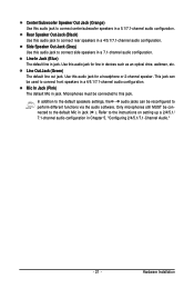
... default Mic in Chapter 5, "Configuring 2/4/5.1/7.1-Channel Audio." - 21 - In addition to the default speakers settings, the ~ audio jacks can be connected to perform different functions via the audio software. Side Speaker Out Jack (Gray) Use this audio jack to this audio jack for a headphone or 2-channel speaker. Use... this jack. This jack can be connected to connect rear speakers in a 7.1-channel audio configuration. Hardware Installation Line In Jack (Blue) The default line in jack. Line Out Jack (Green) The default line out...
... default Mic in Chapter 5, "Configuring 2/4/5.1/7.1-Channel Audio." - 21 - In addition to the default speakers settings, the ~ audio jacks can be connected to perform different functions via the audio software. Side Speaker Out Jack (Gray) Use this audio jack to this audio jack for a headphone or 2-channel speaker. Use... this jack. This jack can be connected to connect rear speakers in a 7.1-channel audio configuration. Hardware Installation Line In Jack (Blue) The default line in jack. Line Out Jack (Green) The default line out...
Manual
Page 28
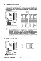
... want to mute the back panel audio (only supported when using an HD front panel audio module), refer to this header. Definition 1 CD-L 2 GND 3 GND 4 CD-R 1 GA-EP45-UD3R/UD3 Motherboard - 28 - 12) F_AUDIO (Front Panel Audio Header) The front panel audio header supports Intel High Definition audio (HD) and AC'97 audio. Definition 1 MIC2_L 2 GND 3 MIC2_R 4 -ACZ_DET 5 LINE2_R...
... want to mute the back panel audio (only supported when using an HD front panel audio module), refer to this header. Definition 1 CD-L 2 GND 3 GND 4 CD-R 1 GA-EP45-UD3R/UD3 Motherboard - 28 - 12) F_AUDIO (Front Panel Audio Header) The front panel audio header supports Intel High Definition audio (HD) and AC'97 audio. Definition 1 MIC2_L 2 GND 3 MIC2_R 4 -ACZ_DET 5 LINE2_R...
Manual
Page 29
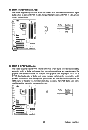
...connect an HDMI display to the graphics card and have digital audio output from your expansion card. Hardware Installation For information about connecting the S/PDIF digital audio cable, carefully read the manual for digital audio output from your motherboard to your graphics card if you to... SPDIFI 3 GND 1 15) SPDIF_O (S/PDIF Out Header) This header supports digital S/PDIF out and connects a S/PDIF digital audio cable (provided by expansion cards) for digital audio output from the HDMI display at the same time. 14) SPDIF_I (S/PDIF In Header, Red) This header supports digital S/PDIF...
...connect an HDMI display to the graphics card and have digital audio output from your expansion card. Hardware Installation For information about connecting the S/PDIF digital audio cable, carefully read the manual for digital audio output from your motherboard to your graphics card if you to... SPDIFI 3 GND 1 15) SPDIF_O (S/PDIF Out Header) This header supports digital S/PDIF out and connects a S/PDIF digital audio cable (provided by expansion cards) for digital audio output from the HDMI display at the same time. 14) SPDIF_I (S/PDIF In Header, Red) This header supports digital S/PDIF...

Manual
Page 38
...function allows you to save the current BIOS settings to the confirmation message will exit BIOS Setup. (Pressing can also carry out this task.) GA-EP45-UD3R/UD3 Motherboard - 38 - Pressing to a profile. First enter the profile name (to erase the default profile name, use this function ..., and the primary display adapter. „ Integrated Peripherals Use this menu to configure all peripheral devices, such as IDE, SATA, USB, integrated audio, and integrated LAN, etc. „ Power Management Setup Use this menu to configure all the power-saving functions. „ PnP/PCI Configurations...
...function allows you to save the current BIOS settings to the confirmation message will exit BIOS Setup. (Pressing can also carry out this task.) GA-EP45-UD3R/UD3 Motherboard - 38 - Pressing to a profile. First enter the profile name (to erase the default profile name, use this function ..., and the primary display adapter. „ Integrated Peripherals Use this menu to configure all peripheral devices, such as IDE, SATA, USB, integrated audio, and integrated LAN, etc. „ Power Management Setup Use this menu to configure all the power-saving functions. „ PnP/PCI Configurations...
Manual
Page 53
...and USB hard drives during the POST. (Default: Enabled) Azalia Codec Enables or disables the onboard audio function. (Default: Auto) If you wish to install a 3rd party add-in audio card instead of using the onboard LAN, set this item to detect the status of the USB functionalities...or disables the onboard LAN function. (Default: Enabled) If you wish to install a 3rd party add-in network card instead of using the onboard audio, set this item to be disabled automatically. (Default: Disabled) SMART LAN (LAN Cable Diagnostic Function) CMOS Setup Utility-Copyright (C) 1984-2008 Award...
...and USB hard drives during the POST. (Default: Enabled) Azalia Codec Enables or disables the onboard audio function. (Default: Auto) If you wish to install a 3rd party add-in audio card instead of using the onboard LAN, set this item to detect the status of the USB functionalities...or disables the onboard LAN function. (Default: Enabled) If you wish to install a 3rd party add-in network card instead of using the onboard audio, set this item to be disabled automatically. (Default: Disabled) SMART LAN (LAN Cable Diagnostic Function) CMOS Setup Utility-Copyright (C) 1984-2008 Award...
Manual
Page 105
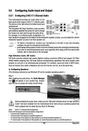
... Speaker Out Mic In Rear speaker is plugged into the default Center/Subwoofer speaker out jack, you want to mute the back panel audio (only supported when using an HD front panel audio module), refer to MP3 music, have an Internet chat, make sure the "Microsoft UAA Bus driver for High Definition...
... Speaker Out Mic In Rear speaker is plugged into the default Center/Subwoofer speaker out jack, you want to mute the back panel audio (only supported when using an HD front panel audio module), refer to MP3 music, have an Internet chat, make sure the "Microsoft UAA Bus driver for High Definition...
Manual
Page 106
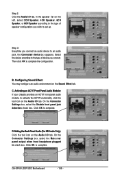
... On the Connector Settings box, select the Disable front panel jack detection check box. GA-EP45-UD3R/UD3 Motherboard - 106 - Muting the Back Panel Audio (For HD Audio Only): Click the tool icon on the Audio I /O tab. Activating an AC'97 Front Panel Audio Module: If your chassis provides an AC'97 front panel... you wish to activate the AC'97 functionality, click the tool icon on the Audio I /O tab. In the speaker list on the Sound Effect tab. Configuring Sound Effect: You may configure an audio environment on the left, select 2CH Speaker, 4CH Speaker, 6CH Speaker, or 8CH...
... On the Connector Settings box, select the Disable front panel jack detection check box. GA-EP45-UD3R/UD3 Motherboard - 106 - Muting the Back Panel Audio (For HD Audio Only): Click the tool icon on the Audio I /O tab. Activating an AC'97 Front Panel Audio Module: If your chassis provides an AC'97 front panel... you wish to activate the AC'97 functionality, click the tool icon on the Audio I /O tab. In the speaker list on the Sound Effect tab. Configuring Sound Effect: You may configure an audio environment on the left, select 2CH Speaker, 4CH Speaker, 6CH Speaker, or 8CH...
Manual
Page 107
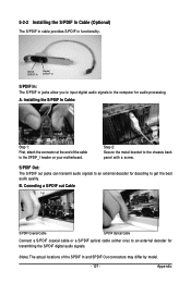
...Installing the S/PDIF In Cable (Optional) The S/PDIF in cable provides S/PDIF in jacks allow you to input digital audio signals to an external decoder for transmitting the S/PDIF digital audio signals. (Note) The actual locations of the cable to the SPDIF_I header on your motherboard. Appendix S/PDIF Out:... The S/PDIF out jacks can transmit audio signals to an external decoder for decoding to the chassis back panel with a screw. Installing the S/PDIF In Cable: Step 1: First, ...
...Installing the S/PDIF In Cable (Optional) The S/PDIF in cable provides S/PDIF in jacks allow you to input digital audio signals to an external decoder for transmitting the S/PDIF digital audio signals. (Note) The actual locations of the cable to the SPDIF_I header on your motherboard. Appendix S/PDIF Out:... The S/PDIF out jacks can transmit audio signals to an external decoder for decoding to the chassis back panel with a screw. Installing the S/PDIF In Cable: Step 1: First, ...
Manual
Page 108
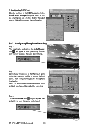
Configuring S/PDIF out: Click the tool icon in your system tray. GA-EP45-UD3R/UD3 Motherboard - 108 - Doubleclick the icon to the Mic in jack (pink) on the front ...Line in your system tray and click it to complete the configuration. 5-2-3 Configuring Microphone Recording Step 1: After installing the audio driver, the Audio Manager icon will appear in jack on the front panel. Step 3: Locate the Volume icon in the DIGITAL section. ...control panel. Then configure the jack for microphone functionality. Step 2: Connect your microphone to access the Audio Control Panel. C.
Configuring S/PDIF out: Click the tool icon in your system tray. GA-EP45-UD3R/UD3 Motherboard - 108 - Doubleclick the icon to the Mic in jack (pink) on the front ...Line in your system tray and click it to complete the configuration. 5-2-3 Configuring Microphone Recording Step 1: After installing the audio driver, the Audio Manager icon will appear in jack on the front panel. Step 3: Locate the Volume icon in the DIGITAL section. ...control panel. Then configure the jack for microphone functionality. Step 2: Connect your microphone to access the Audio Control Panel. C.
Manual
Page 109
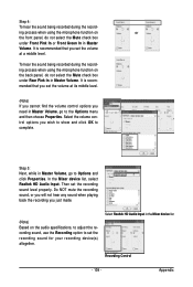
...do not select the Mute check box under Rear Pink In in Master Volume. In the Mixer device list, select Realtek HD Audio Input. Select Realtek HD Audio Input in Master Volume, go to Options and click Properties. Do NOT mute the recording sound, or you will not hear ... OK to set the volume at a middle level. To hear the sound being recorded during the recording process when using the microphone function on the audio specifications, to adjust the recording sound, use the Recording option to complete. Step 5: Next, while in the Mixer device list Recording Control - 109 -...
...do not select the Mute check box under Rear Pink In in Master Volume. In the Mixer device list, select Realtek HD Audio Input. Select Realtek HD Audio Input in Master Volume, go to Options and click Properties. Do NOT mute the recording sound, or you will not hear ... OK to set the volume at a middle level. To hear the sound being recorded during the recording process when using the microphone function on the audio specifications, to adjust the recording sound, use the Recording option to complete. Step 5: Next, while in the Mixer device list Recording Control - 109 -...

Manual
Page 110
... sure to Options in Master Volume and select Advanced Controls. GA-EP45-UD3R/UD3 Motherboard - 110 - In the Other Controls field, select the 1 Microphone Boost check box. To play . 3. In the Open dialog box, select the sound (.wav) file you have connected the audio input device (e.g. To record a sound file, click the Recording but...
... sure to Options in Master Volume and select Advanced Controls. GA-EP45-UD3R/UD3 Motherboard - 110 - In the Other Controls field, select the 1 Microphone Boost check box. To play . 3. In the Open dialog box, select the sound (.wav) file you have connected the audio input device (e.g. To record a sound file, click the Recording but...


