
User Manual
Page 2
Motherboard GA-A75-D3H Jun. 13, 2011 Motherboard GA-A75-D3H Jun. 13, 2011
Motherboard GA-A75-D3H Jun. 13, 2011 Motherboard GA-A75-D3H Jun. 13, 2011
User Manual
Page 3
...their respective owners. For product-related information, check on our website at: http://www.gigabyte.com Identifying Your Motherboard Revision The revision number on your motherboard revision before updating motherboard BIOS, drivers, or when looking for technical information. All rights reserved. The trademarks ...TECHNOLOGY CO., LTD. For example, "REV: 1.0" means the revision of the motherboard is the property of this manual is protected by copyright laws and is 1.0. Check your motherboard looks like this manual are legally registered to assist in any means without prior ...
...their respective owners. For product-related information, check on our website at: http://www.gigabyte.com Identifying Your Motherboard Revision The revision number on your motherboard revision before updating motherboard BIOS, drivers, or when looking for technical information. All rights reserved. The trademarks ...TECHNOLOGY CO., LTD. For example, "REV: 1.0" means the revision of the motherboard is the property of this manual is protected by copyright laws and is 1.0. Check your motherboard looks like this manual are legally registered to assist in any means without prior ...
User Manual
Page 4
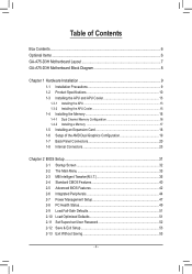
Table of Contents Box Contents...6 Optional Items...6 GA-A75-D3H Motherboard Layout 7 GA-A75-D3H Motherboard Block Diagram 8 Chapter 1 Hardware Installation 9 1-1 Installation Precautions 9 1-2 Product Specifications 10 1-3 Installing the APU and APU Cooler 13 1-3-1 Installing the APU...13 1-3-2 Installing the APU Cooler ...
Table of Contents Box Contents...6 Optional Items...6 GA-A75-D3H Motherboard Layout 7 GA-A75-D3H Motherboard Block Diagram 8 Chapter 1 Hardware Installation 9 1-1 Installation Precautions 9 1-2 Product Specifications 10 1-3 Installing the APU and APU Cooler 13 1-3-1 Installing the APU...13 1-3-2 Installing the APU Cooler ...

User Manual
Page 6
The box contents are for reference only and the actual items shall depend on the product package you obtain. Optional Items 2-port USB 2.0 bracket (Part No. 12CR1-1UB030-5*R) 2-port SATA power cable (Part No. 12CF1-2SERPW-0*R) COM port cable (Part No. 12CF1-1CM001-3*R) 3.5" Front Panel with 2 USB 3.0/2.0 ports (Part No. 12CR1-FPX582-0*R) - 6 - Box Contents GA-A75-D3H motherboard Motherboard driver disk User's Manual Quick Installation Guide Four SATA cables I/O Shield The box contents above are subject to change without notice.
The box contents are for reference only and the actual items shall depend on the product package you obtain. Optional Items 2-port USB 2.0 bracket (Part No. 12CR1-1UB030-5*R) 2-port SATA power cable (Part No. 12CF1-2SERPW-0*R) COM port cable (Part No. 12CF1-1CM001-3*R) 3.5" Front Panel with 2 USB 3.0/2.0 ports (Part No. 12CR1-FPX582-0*R) - 6 - Box Contents GA-A75-D3H motherboard Motherboard driver disk User's Manual Quick Installation Guide Four SATA cables I/O Shield The box contents above are subject to change without notice.

User Manual
Page 7
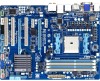
GA-A75-D3H Motherboard Layout KB_MS_USB3 VGA_DVI SYS_FAN2 ATX_12V CPU_FAN Socket FM1 HDMI_SPDIF USB_ESATA PWR_FAN USB30_LAN Etron EJ168 AUDIO PCIEX1_1 Realtek RTL8111E PCIEX16 GA-A75-D3H PCIEX1_2 CODEC PCI1 BAT B_BIOS M_BIOS PCIEX4 iTE IT8720 PCI2 PCI3 F_AUDIO DDR3_4 DDR3_2 DDR3_3 DDR3_1 ATX SATA3_4 SYS_FAN AMD A75 SATA3_3 SATA3_2 SATA3_1 SATA3_0 CLR_CMOS F_PANEL SPDIF_O COM TPM F_USB3 F_USB1 F_USB4 F_USB2 F_USB30 - 7 -
GA-A75-D3H Motherboard Layout KB_MS_USB3 VGA_DVI SYS_FAN2 ATX_12V CPU_FAN Socket FM1 HDMI_SPDIF USB_ESATA PWR_FAN USB30_LAN Etron EJ168 AUDIO PCIEX1_1 Realtek RTL8111E PCIEX16 GA-A75-D3H PCIEX1_2 CODEC PCI1 BAT B_BIOS M_BIOS PCIEX4 iTE IT8720 PCI2 PCI3 F_AUDIO DDR3_4 DDR3_2 DDR3_3 DDR3_1 ATX SATA3_4 SYS_FAN AMD A75 SATA3_3 SATA3_2 SATA3_1 SATA3_0 CLR_CMOS F_PANEL SPDIF_O COM TPM F_USB3 F_USB1 F_USB4 F_USB2 F_USB30 - 7 -

User Manual
Page 8
GA-A75-D3H Motherboard Block Diagram 1 PCI Express x16 PCIe CLK (100 MHz) 2 PCI Express x1 x16 x1 x1 AMD APU APU CLK+/- (100 MHz) DISP CLK+/- (100 MHz) ... PCI Express Bus x1 Realtek UMI 1 PCI Express x4 RTL8111E RJ45 LAN 2 USB 3.0/2.0 PCIe CLK (100 MHz) Etron EJ168 x4 x1 PCI Express Bus AMD A75 D-Sub 4 USB 3.0/2.0 10 USB 2.0/1.1 Dual BIOS PCI Bus 6 SATA 6Gb/s CODEC LPC Bus iTE IT8720 COM Port PS/2 KB/Mouse Surround Speaker Out Center/Subwoofer...
GA-A75-D3H Motherboard Block Diagram 1 PCI Express x16 PCIe CLK (100 MHz) 2 PCI Express x1 x16 x1 x1 AMD APU APU CLK+/- (100 MHz) DISP CLK+/- (100 MHz) ... PCI Express Bus x1 Realtek UMI 1 PCI Express x4 RTL8111E RJ45 LAN 2 USB 3.0/2.0 PCIe CLK (100 MHz) Etron EJ168 x4 x1 PCI Express Bus AMD A75 D-Sub 4 USB 3.0/2.0 10 USB 2.0/1.1 Dual BIOS PCI Bus 6 SATA 6Gb/s CODEC LPC Bus iTE IT8720 COM Port PS/2 KB/Mouse Surround Speaker Out Center/Subwoofer...

User Manual
Page 9
...computer power during the installation process can become damaged as a result of your dealer. Chapter 1 Hardware Installation 1-1 Installation Precautions The motherboard contains numerous delicate electronic circuits and components which can lead to damage to system components as well as physical harm to the user...wrist strap, keep your hands dry and first touch a metal object to eliminate static electricity. • Prior to installing the motherboard, please have a problem related to the local voltage standard. • Before using the product, please verify that all cables and...
...computer power during the installation process can become damaged as a result of your dealer. Chapter 1 Hardware Installation 1-1 Installation Precautions The motherboard contains numerous delicate electronic circuits and components which can lead to damage to system components as well as physical harm to the user...wrist strap, keep your hands dry and first touch a metal object to eliminate static electricity. • Prior to installing the motherboard, please have a problem related to the local voltage standard. • Before using the product, please verify that all cables and...

User Manual
Page 12
... Center ŠŠ Support for Xpress Install ŠŠ Support for Xpress Recovery2 ŠŠ Support for EasyTune * Available functions in EasyTune may differ by motherboard model. ŠŠ Support for Smart Recovery ŠŠ Support for Auto Green ŠŠ Support for ON/OFF Charge ŠŠ Support for 3TB...
... Center ŠŠ Support for Xpress Install ŠŠ Support for Xpress Recovery2 ŠŠ Support for EasyTune * Available functions in EasyTune may differ by motherboard model. ŠŠ Support for Smart Recovery ŠŠ Support for Auto Green ŠŠ Support for ON/OFF Charge ŠŠ Support for 3TB...
User Manual
Page 13
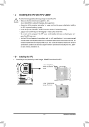
... standard requirements for the latest APU support list.) • Always turn on the computer if the APU cooler is not recommended that the motherboard supports the APU. (Go to GIGABYTE's website for the peripherals. Hardware Installation A Small Triangle Mark Denotes Pin One of the APU may occur. • Set the APU host...
... standard requirements for the latest APU support list.) • Always turn on the computer if the APU cooler is not recommended that the motherboard supports the APU. (Go to GIGABYTE's website for the peripherals. Hardware Installation A Small Triangle Mark Denotes Pin One of the APU may occur. • Set the APU host...

User Manual
Page 14
... middle of the APU, lowering the locking lever and latching it into the socket. Follow the steps below to correctly install the APU into the motherboard APU socket. • Before installing the APU, make sure to turn off the computer and unplug the power cord from the power outlet to prevent...
... middle of the APU, lowering the locking lever and latching it into the socket. Follow the steps below to correctly install the APU into the motherboard APU socket. • Before installing the APU, make sure to turn off the computer and unplug the power cord from the power outlet to prevent...

User Manual
Page 15
1-3-2 Installing the APU Cooler Follow the steps below to correctly install the APU cooler on the APU. (The following procedure uses the GIGABYTE cooler as the picture above shows) to lock into place. (Refer to your APU cooler installation manual for instructions on installing the cooler.) Step... 5: Finally, attach the power connector of the APU cooler to the APU fan header (CPU_FAN) on the motherboard. Hardware Installation Step 4: Turn the cam handle from the left side to the mounting lug on one side of the installed APU. Step 3: ...
1-3-2 Installing the APU Cooler Follow the steps below to correctly install the APU cooler on the APU. (The following procedure uses the GIGABYTE cooler as the picture above shows) to lock into place. (Refer to your APU cooler installation manual for instructions on installing the cooler.) Step... 5: Finally, attach the power connector of the APU cooler to the APU fan header (CPU_FAN) on the motherboard. Hardware Installation Step 4: Turn the cam handle from the left side to the mounting lug on one side of the installed APU. Step 3: ...

User Manual
Page 16
...memory sockets as following guidelines before installing the memory to insert the memory, switch the direction. 1-4-1 Dual Channel Memory Configuration This motherboard provides four DDR3 memory sockets and supports Dual Channel Technology. The four DDR3 memory sockets are installed. (Dual channel memory mode ...installed in the same colored DDR3 sockets. When enabling Dual Channel mode with two memory modules, we recommend that you begin to GIGABYTE's website for the latest supported memory speeds and memory modules.) • Always turn off the computer and unplug the power cord...
...memory sockets as following guidelines before installing the memory to insert the memory, switch the direction. 1-4-1 Dual Channel Memory Configuration This motherboard provides four DDR3 memory sockets and supports Dual Channel Technology. The four DDR3 memory sockets are installed. (Dual channel memory mode ...installed in the same colored DDR3 sockets. When enabling Dual Channel mode with two memory modules, we recommend that you begin to GIGABYTE's website for the latest supported memory speeds and memory modules.) • Always turn off the computer and unplug the power cord...

User Manual
Page 17
... left, place your memory modules in the memory sockets. Step 2: The clips at both ends of the memory module. Place the memory module on this motherboard. Step 1: Note the orientation of the socket will snap into the memory socket. Hardware Installation Notch DDR3 DIMM A DDR3 memory module has a notch, so it...
... left, place your memory modules in the memory sockets. Step 2: The clips at both ends of the memory module. Place the memory module on this motherboard. Step 1: Note the orientation of the socket will snap into the memory socket. Hardware Installation Notch DDR3 DIMM A DDR3 memory module has a notch, so it...

User Manual
Page 18
... on the card are completely inserted into the PCI Express slot. Secure the card's metal bracket to install an expansion card: • Make sure the motherboard supports the expansion card. Hardware Installation - 18 - • Removing the Card from the PCIEX4 Slot: Press the latch at the end of the card until...
... on the card are completely inserted into the PCI Express slot. Secure the card's metal bracket to install an expansion card: • Make sure the motherboard supports the expansion card. Hardware Installation - 18 - • Removing the Card from the PCIEX4 Slot: Press the latch at the end of the card until...
User Manual
Page 19
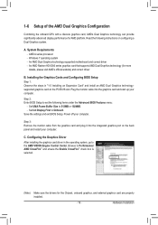
System Requirements - Save the settings and exit BIOS Setup. Hardware Installation A. An AMD Dual Graphics technology-supported motherboard and correct driver - Set Init Display First to 512MB or 1024MB. - Step 3: Remove the monitor cable from the graphics card and plug it into the ...
System Requirements - Save the settings and exit BIOS Setup. Hardware Installation A. An AMD Dual Graphics technology-supported motherboard and correct driver - Set Init Display First to 512MB or 1024MB. - Step 3: Remove the monitor cable from the graphics card and plug it into the ...
User Manual
Page 21
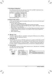
... Features," for USB devices such as a USB keyboard/mouse, USB printer, USB flash drive and etc. Playback of the LAN port LEDs. The AMD A75 Chipset supports RAID function. Whether Hardware Acceleration can be enabled for instructions on the device being used.) • HDCP compliant monitor(s) USB 2.0/1.1 Port The...) • Playback software: CyberLink PowerDVD 10.0 or later (Note: Please ensure Hardware Acceleration is dependent on configuring a RAID array. Dual Display Configurations: This motherboard provides three video output ports: D-Sub, DVI-D, and HDMI.
... Features," for USB devices such as a USB keyboard/mouse, USB printer, USB flash drive and etc. Playback of the LAN port LEDs. The AMD A75 Chipset supports RAID function. Whether Hardware Acceleration can be enabled for instructions on the device being used.) • HDCP compliant monitor(s) USB 2.0/1.1 Port The...) • Playback software: CyberLink PowerDVD 10.0 or later (Note: Please ensure Hardware Acceleration is dependent on configuring a RAID array. Dual Display Configurations: This motherboard provides three video output ports: D-Sub, DVI-D, and HDMI.

User Manual
Page 22
... a back panel connector, first remove the cable from your device and then remove it from the connector. Do not rock it straight out from the motherboard. • When removing the cable, pull it side to side to prevent an electrical short inside the cable connector.
... a back panel connector, first remove the cable from your device and then remove it from the connector. Do not rock it straight out from the motherboard. • When removing the cable, pull it side to side to prevent an electrical short inside the cable connector.

User Manual
Page 23
..., make sure your devices are compliant with the connectors you wish to connect. • Before installing the devices, be sure to the connector on the motherboard. - 23 -
..., make sure your devices are compliant with the connectors you wish to connect. • Before installing the devices, be sure to the connector on the motherboard. - 23 -

User Manual
Page 24
If a power supply is turned off and all the components on the motherboard. Connect the power supply cable to the APU. 1/2) ATX_12V/ATX (2x4 12V Power Connector and 2x12 Main Power Connector) With the use of the power ...
If a power supply is turned off and all the components on the motherboard. Connect the power supply cable to the APU. 1/2) ATX_12V/ATX (2x4 12V Power Connector and 2x12 Main Power Connector) With the use of the power ...

User Manual
Page 25
...in the power cord and restart your computer. • Always turn off your - Plug in accordance with fan speed control design. The motherboard supports APU fan speed control, which requires the use a metal object like a screwdriver to keep the values (such as BIOS configurations, ...; Be sure to connect fan cables to the fan headers to replace the battery by removing the battery: 1. 3/4/5) CPU_FAN/SYS_FAN/SYS_FAN2/PWR_FAN (Fan Headers) The motherboard has a 4-pin CPU fan header (CPU_FAN), a 4-pin (SYS_FAN) and a 3-pin (SYS_FAN2) system fan headers, and a 3-pin power fan header (...
...in the power cord and restart your computer. • Always turn off your - Plug in accordance with fan speed control design. The motherboard supports APU fan speed control, which requires the use a metal object like a screwdriver to keep the values (such as BIOS configurations, ...; Be sure to connect fan cables to the fan headers to replace the battery by removing the battery: 1. 3/4/5) CPU_FAN/SYS_FAN/SYS_FAN2/PWR_FAN (Fan Headers) The motherboard has a 4-pin CPU fan header (CPU_FAN), a 4-pin (SYS_FAN) and a 3-pin (SYS_FAN2) system fan headers, and a 3-pin power fan header (...


