
User Manual
Page 1
GA-A75-D3H User's Manual Rev. 1002 12ME-A75D3H-1002R
GA-A75-D3H User's Manual Rev. 1002 12ME-A75D3H-1002R
User Manual
Page 3
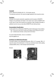
... the Quick Installation Guide included with the product. For detailed product information, carefully read the User's Manual. Disclaimer Information in this : "REV: X.X." For product-related information, check on our website at: http://www.gigabyte.com Identifying Your Motherboard Revision The revision number on your motherboard revision before updating motherboard BIOS, drivers...
... the Quick Installation Guide included with the product. For detailed product information, carefully read the User's Manual. Disclaimer Information in this : "REV: X.X." For product-related information, check on our website at: http://www.gigabyte.com Identifying Your Motherboard Revision The revision number on your motherboard revision before updating motherboard BIOS, drivers...

User Manual
Page 5
Chapter 3 Drivers Installation 55 3-1 Installing Chipset Drivers 55 3-2 Application Software 56 3-3 Technical Manuals 56 3-4 Contact...57 3-5 System...57 3-6 Download Center 58 3-7 New Utilities...58 Chapter 4 Unique Features 59 4-1 Xpress Recovery2 59 4-2 BIOS Update Utilities 62 4-2-1 Updating the BIOS ...
Chapter 3 Drivers Installation 55 3-1 Installing Chipset Drivers 55 3-2 Application Software 56 3-3 Technical Manuals 56 3-4 Contact...57 3-5 System...57 3-6 Download Center 58 3-7 New Utilities...58 Chapter 4 Unique Features 59 4-1 Xpress Recovery2 59 4-2 BIOS Update Utilities 62 4-2-1 Updating the BIOS ...

User Manual
Page 6
The box contents are for reference only and the actual items shall depend on the product package you obtain. Optional Items 2-port USB 2.0 bracket (Part No. 12CR1-1UB030-5*R) 2-port SATA power cable (Part No. 12CF1-2SERPW-0*R) COM port cable (Part No. 12CF1-1CM001-3*R) 3.5" Front Panel with 2 USB 3.0/2.0 ports (Part No. 12CR1-FPX582-0*R) - 6 - Box Contents GA-A75-D3H motherboard Motherboard driver disk User's Manual Quick Installation Guide Four SATA cables I/O Shield The box contents above are subject to change without notice.
The box contents are for reference only and the actual items shall depend on the product package you obtain. Optional Items 2-port USB 2.0 bracket (Part No. 12CR1-1UB030-5*R) 2-port SATA power cable (Part No. 12CF1-2SERPW-0*R) COM port cable (Part No. 12CF1-1CM001-3*R) 3.5" Front Panel with 2 USB 3.0/2.0 ports (Part No. 12CR1-FPX582-0*R) - 6 - Box Contents GA-A75-D3H motherboard Motherboard driver disk User's Manual Quick Installation Guide Four SATA cables I/O Shield The box contents above are subject to change without notice.

User Manual
Page 9
ponents such as a motherboard, APU or memory. Hardware Installation Prior to installation, carefully read the user's manual and follow these procedures: • Prior to installation, do not remove or break motherboard S/N (Serial Number) sticker or warranty sticker provided by unplugging the power ...
ponents such as a motherboard, APU or memory. Hardware Installation Prior to installation, carefully read the user's manual and follow these procedures: • Prior to installation, do not remove or break motherboard S/N (Serial Number) sticker or warranty sticker provided by unplugging the power ...

User Manual
Page 15
... to hook it to correctly install the APU cooler on the APU. (The following procedure uses the GIGABYTE cooler as the picture above shows) to lock into place. (Refer to your APU cooler installation manual for instructions on installing the cooler.) Step 5: Finally, attach the power connector of the retention frame. Inadequately...
... to hook it to correctly install the APU cooler on the APU. (The following procedure uses the GIGABYTE cooler as the picture above shows) to lock into place. (Refer to your APU cooler installation manual for instructions on installing the cooler.) Step 5: Finally, attach the power connector of the retention frame. Inadequately...

User Manual
Page 18
1-5 Installing an Expansion Card Read the following guidelines before installing an expansion card to prevent hardware damage. Carefully read the manual that supports your card. Remove the metal slot cover from the PCIEX4 Slot: Press the latch at the end of the card until it is ...
1-5 Installing an Expansion Card Read the following guidelines before installing an expansion card to prevent hardware damage. Carefully read the manual that supports your card. Remove the metal slot cover from the PCIEX4 Slot: Press the latch at the end of the card until it is ...

User Manual
Page 26
...8226; A RAID 0 or RAID 1 configuration requires at least two hard drives. Hardware Installation - 26 - Each SATA connector supports a single SATA device. The AMD A75 Chipset supports RAID 0, RAID 1, RAID 10, and JBOD. Refer to touch the two pins for BIOS configurations). SATA3_1 7 7 SATA3_0 G.QBOFM G.QBOFM 1 7 SATA3_3... the motherboard. •• After system restart, go to BIOS Setup to load factory defaults (select Load Optimized Defaults) or manually configure the BIOS settings (refer to remove the jumper cap from the power outlet before clearing the CMOS values. •• ...
...8226; A RAID 0 or RAID 1 configuration requires at least two hard drives. Hardware Installation - 26 - Each SATA connector supports a single SATA device. The AMD A75 Chipset supports RAID 0, RAID 1, RAID 10, and JBOD. Refer to touch the two pins for BIOS configurations). SATA3_1 7 7 SATA3_0 G.QBOFM G.QBOFM 1 7 SATA3_3... the motherboard. •• After system restart, go to BIOS Setup to load factory defaults (select Load Optimized Defaults) or manually configure the BIOS settings (refer to remove the jumper cap from the power outlet before clearing the CMOS values. •• ...

User Manual
Page 28
... and have digital audio output from the HDMI display at the same time. For information about connecting the S/PDIF digital audio cable, carefully read the manual for digital audio output from your chassis provides an AC'97 front panel audio module, refer1 to the instructions on each wire instead of the...
... and have digital audio output from the HDMI display at the same time. For information about connecting the S/PDIF digital audio cable, carefully read the manual for digital audio output from your chassis provides an AC'97 front panel audio module, refer1 to the instructions on each wire instead of the...
User Manual
Page 36
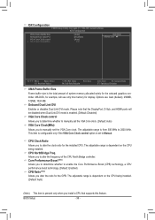
...the CPU being installed. (Default: Auto) (Note) This item is set to 2000 MHz. The adjustable range is from 300 MHz to Manual. IGX Configuration CMOS Setup Utility-Copyright (C) 1984-2011 Award Software IGX Configuration UMA Frame Buffer Size Onboard Dual Link DVI VGA Core Clock ... whether to enable the Core Performance Boost (CPB) technology, a CPU performance-boost technology. (Default: Enabled) CPB Ratio (Note) Allows you to manually set the VGA Core clock. (Default: Auto) VGA Core Clock(MHz) Allows you alter the ratio for the onboard graphics controller. Please note that...
...the CPU being installed. (Default: Auto) (Note) This item is set to 2000 MHz. The adjustable range is from 300 MHz to Manual. IGX Configuration CMOS Setup Utility-Copyright (C) 1984-2011 Award Software IGX Configuration UMA Frame Buffer Size Onboard Dual Link DVI VGA Core Clock ... whether to enable the Core Performance Boost (CPB) technology, a CPU performance-boost technology. (Default: Enabled) CPB Ratio (Note) Allows you to manually set the VGA Core clock. (Default: Auto) VGA Core Clock(MHz) Allows you alter the ratio for the onboard graphics controller. Please note that...

User Manual
Page 37
...Sets Memory Clock to X5.33. BIOS Setup PCIe Spread Spectrum Enables or disables PCIe Spread Spectrum. (Default: Disabled) Set Memory Clock Determines whether to Manual. Auto -9T 9T 9T 24T 5T 110ns -6T 4T 20T 4T -- Important It is set the memory clock as required. CPU Host Clock Control ...Enables or disables the control of CPU host clock. X5.33 Sets Memory Clock to X9.33. Options are: Auto (default), Manual. 1T/2T Command Timing Options are: Auto (default), 1T, 2T. Auto (default) allows the BIOS to be set the memory clock. Item Help Menu...
...Sets Memory Clock to X5.33. BIOS Setup PCIe Spread Spectrum Enables or disables PCIe Spread Spectrum. (Default: Disabled) Set Memory Clock Determines whether to Manual. Auto -9T 9T 9T 24T 5T 110ns -6T 4T 20T 4T -- Important It is set the memory clock as required. CPU Host Clock Control ...Enables or disables the control of CPU host clock. X5.33 Sets Memory Clock to X9.33. Options are: Auto (default), Manual. 1T/2T Command Timing Options are: Auto (default), 1T, 2T. Auto (default) allows the BIOS to be set the memory clock. Item Help Menu...

User Manual
Page 38
...(default), 16T~40T. Note: Increasing CPU voltage may result in damage to 2.900V. Row Cycle Time Options are : Auto (default), 15T~36T. Manual allows all voltage control items below to be configurable. (Default: Auto) CPU PLL Voltage Control Allows you to 2.135V. Minimum RAS Active Time Options ... 20T~54T. Normal Supplies the CPU PLL voltage as required. Auto lets the BIOS automatically set the system voltages. Enabled allows the system to manually set the system voltages as required. (Default) 2.100V ~ 2.900V The adjustable range is from 2.100V to your CPU or reduce the useful...
...(default), 16T~40T. Note: Increasing CPU voltage may result in damage to 2.900V. Row Cycle Time Options are : Auto (default), 15T~36T. Manual allows all voltage control items below to be configurable. (Default: Auto) CPU PLL Voltage Control Allows you to 2.135V. Minimum RAS Active Time Options ... 20T~54T. Normal Supplies the CPU PLL voltage as required. Auto lets the BIOS automatically set the system voltages. Enabled allows the system to manually set the system voltages as required. (Default) 2.100V ~ 2.900V The adjustable range is from 2.100V to your CPU or reduce the useful...

User Manual
Page 55
... Windows XP operating system, please install the Windows XP Service Pack 1 or later. Or click Install Single Items to manually select the drivers you want to manually select the utilities to install new GIGABYTE utilities. Click Yes to install other drivers. • After "Xpress Install" installs all the recommended drivers. Or click No...
... Windows XP operating system, please install the Windows XP Service Pack 1 or later. Or click Install Single Items to manually select the drivers you want to manually select the utilities to install new GIGABYTE utilities. Click Yes to install other drivers. • After "Xpress Install" installs all the recommended drivers. Or click No...

User Manual
Page 56
You can click the Install button on the right of an item to install it. 3-3 Technical Manuals This page provides GIGABYTE's application guides, content descriptions for this driver disk, and the motherboard manuals. Drivers Installation - 56 - 3-2 Application Software This page displays all the utilities and applications that GIGABYTE develops and some free software.
You can click the Install button on the right of an item to install it. 3-3 Technical Manuals This page provides GIGABYTE's application guides, content descriptions for this driver disk, and the motherboard manuals. Drivers Installation - 56 - 3-2 Application Software This page displays all the utilities and applications that GIGABYTE develops and some free software.

User Manual
Page 62
...the need to access Q-Flash. GA-A75-D3H E12 . . . . : BIOS Setup : XpressRecovery2 : Boot Menu : Qflash 05/26/2011-Llano-Hudson-7A66HG04C-00 Because BIOS flashing is DualBIOS™? What is potentially risky, please do it with the Q-Flash Utility A. From GIGABYTE's website, download the latest compressed... and stability of going through complicated BIOS flashing process. For the sake of system safety, users cannot update the backup BIOS manually. With Q-Flash you to an independent SATA controller, use the key during the POST or pressing the key in the BIOS...
...the need to access Q-Flash. GA-A75-D3H E12 . . . . : BIOS Setup : XpressRecovery2 : Boot Menu : Qflash 05/26/2011-Llano-Hudson-7A66HG04C-00 Because BIOS flashing is DualBIOS™? What is potentially risky, please do it with the Q-Flash Utility A. From GIGABYTE's website, download the latest compressed... and stability of going through complicated BIOS flashing process. For the sake of system safety, users cannot update the backup BIOS manually. With Q-Flash you to an independent SATA controller, use the key during the POST or pressing the key in the BIOS...

User Manual
Page 65
...system restarts. Unique Features During the BIOS update process, ensure the Internet connection is not present on the @BIOS server site, please manually download the BIOS update file from the Internet or through other source. Using @BIOS 1. Save the Current BIOS File: Click Save ... save the current BIOS file. 4. Follow the on -screen instructions to be flashed matches your motherboard model. Do not use the G.O.M. (GIGABYTE Online Management) function when using @BIOS. 4. Load BIOS Defaults after BIOS Update: Select the Load CMOS default after BIOS update check box ...
...system restarts. Unique Features During the BIOS update process, ensure the Internet connection is not present on the @BIOS server site, please manually download the BIOS update file from the Internet or through other source. Using @BIOS 1. Save the Current BIOS File: Click Save ... save the current BIOS file. 4. Follow the on -screen instructions to be flashed matches your motherboard model. Do not use the G.O.M. (GIGABYTE Online Management) function when using @BIOS. 4. Load BIOS Defaults after BIOS Update: Select the Load CMOS default after BIOS update check box ...

User Manual
Page 74
Option ROM Utility (c) 2011 Advanced Micro Devices, Inc. LD No LD Name LD 1 Logical Drive 1 [ LD Define Menu ] RAID Mode Drv RAID 0 0 Stripe Block Gigabyte Boundary Read Policy 64 KB ON Read Ahead Initialization Fast Write Policy WriteBack [ Drives Assignments ] Port:ID 01:00 02:00 Drive Model WDC WD800JD-... [ESC] Exit Figure 4 In the LD Define Menu, use the up or down arrow key to move to access the LD Define Menu. Create Arrays Manually To create a new array, press to enter the LD View Menu window (Figure 4).
Option ROM Utility (c) 2011 Advanced Micro Devices, Inc. LD No LD Name LD 1 Logical Drive 1 [ LD Define Menu ] RAID Mode Drv RAID 0 0 Stripe Block Gigabyte Boundary Read Policy 64 KB ON Read Ahead Initialization Fast Write Policy WriteBack [ Drives Assignments ] Port:ID 01:00 02:00 Drive Model WDC WD800JD-... [ESC] Exit Figure 4 In the LD Define Menu, use the up or down arrow key to move to access the LD Define Menu. Create Arrays Manually To create a new array, press to enter the LD View Menu window (Figure 4).
User Manual
Page 81
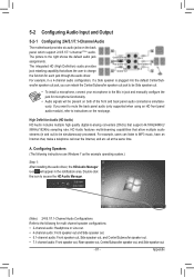
... support 44.1KHz/48KHz/ 96KHz/192KHz sampling rate. For example, users can retask the Center/Subwoofer speaker out jack to the Mic in jack and manually configure the jack for microphone functionality. • Audio signals will appear in a 4-channel audio configuration, if a Side speaker is plugged into the default Center/Sub...
... support 44.1KHz/48KHz/ 96KHz/192KHz sampling rate. For example, users can retask the Center/Subwoofer speaker out jack to the Mic in jack and manually configure the jack for microphone functionality. • Audio signals will appear in a 4-channel audio configuration, if a Side speaker is plugged into the default Center/Sub...

User Manual
Page 91
...GIGABYTE cannot, however, assume any unauthorized purpose. Restriction of disposal will be glad to help to conserve natural resources and ensure that it back" to your local or regional waste collection administration for recycling. ŠŠ If you need further assistance in recycling, reusing in your product's user's manual..., recycling and disposal procedure. The separate collection and recycling of your "end of our natural resources, GIGABYTE provides the following information on its packaging, which indicates that the information in Electrical and Electronic Equipment) and...
...GIGABYTE cannot, however, assume any unauthorized purpose. Restriction of disposal will be glad to help to conserve natural resources and ensure that it back" to your local or regional waste collection administration for recycling. ŠŠ If you need further assistance in recycling, reusing in your product's user's manual..., recycling and disposal procedure. The separate collection and recycling of your "end of our natural resources, GIGABYTE provides the following information on its packaging, which indicates that the information in Electrical and Electronic Equipment) and...


