Manual
Page 1
GA-965P-DS3/S3 Intel® CoreTM 2 Extreme quad-core / CoreTM 2 Quad / Intel® CoreTM 2 Extreme dual-core / CoreTM 2 Duo / Intel® Pentium® Processor Extreme Edition / Intel® Pentium® D / Pentium® 4 / Celeron® D LGA775 Processor Motherboard User's Manual Rev. 3301 12ME-I65PDS3-3301R * The WEEE marking on the product indicates this product must...
GA-965P-DS3/S3 Intel® CoreTM 2 Extreme quad-core / CoreTM 2 Quad / Intel® CoreTM 2 Extreme dual-core / CoreTM 2 Duo / Intel® Pentium® Processor Extreme Edition / Intel® Pentium® D / Pentium® 4 / Celeron® D LGA775 Processor Motherboard User's Manual Rev. 3301 12ME-I65PDS3-3301R * The WEEE marking on the product indicates this product must...
Manual
Page 2
Motherboard GA-965P-DS3 Oct. 20, 2006 Motherboard GA-965P-DS3 Oct. 20, 2006
Motherboard GA-965P-DS3 Oct. 20, 2006 Motherboard GA-965P-DS3 Oct. 20, 2006

Manual
Page 3
Motherboard GA-965P-S3 Jan. 18, 2007 Motherboard GA-965P-S3 Jan. 18, 2007
Motherboard GA-965P-S3 Jan. 18, 2007 Motherboard GA-965P-S3 Jan. 18, 2007
Manual
Page 5
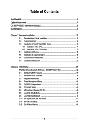
Table of Contents ItemChecklist ...7 OptionalAccessories ...7 GA-965P-DS3/S3 Motherboard Layout 8 Block Diagram ...9 Chapter 1 Hardware Installation 11 1-1 Considerations Prior to Installation 11 1-2 Feature Summary 12 1-3 Installation of the CPU...1-5 Installation of Expansion Cards 18 1-6 I/O Back Panel Introduction 19 1-7 Connectors Introduction 20 Chapter 2 BIOS Setup 31 The Main Menu (Example BIOS Ver.: GA-965P-DS3, F10a 32 2-1 Standard CMOS Features 34 2-2 Advanced BIOS Features 36 2-3 IntegratedPeripherals 38 2-4 Power Management Setup 41 2-5 PnP/PCI Configurations 43 2-6 PC ...
Table of Contents ItemChecklist ...7 OptionalAccessories ...7 GA-965P-DS3/S3 Motherboard Layout 8 Block Diagram ...9 Chapter 1 Hardware Installation 11 1-1 Considerations Prior to Installation 11 1-2 Feature Summary 12 1-3 Installation of the CPU...1-5 Installation of Expansion Cards 18 1-6 I/O Back Panel Introduction 19 1-7 Connectors Introduction 20 Chapter 2 BIOS Setup 31 The Main Menu (Example BIOS Ver.: GA-965P-DS3, F10a 32 2-1 Standard CMOS Features 34 2-2 Advanced BIOS Features 36 2-3 IntegratedPeripherals 38 2-4 Power Management Setup 41 2-5 PnP/PCI Configurations 43 2-6 PC ...
Manual
Page 8
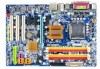
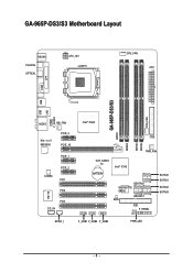
GA-965P-DS3/S3 Motherboard Layout KB_MS COAXIAL OPTICAL ATX_12V LGA775 CPU_FAN ATX COM LPT SYS_FAN GA-965P-DS3/S3 DDRII1 USB USB LAN F_AUDIO AUDIO NB_FAN Marvell 88E8056 PCIE_3 PCIE_16 PCIE_1 CODEC PCIE_2 PCI1 PCI2 IT8718 PCI3 CD_IN Intel® P965 FDD DDRII3 DDRII4 DDRII2 PWR_FAN CLR_CMOS BATTERY Intel® ICH8 GSATAII0 GIGABYTE SATA2 GSATAII1 BIOS IDE1 CI F_PANEL SATAII0 SATAII1 SATAII2 SATAII3 SPDIF_I F_USB1 F_USB2 F_USB3 PWR_LED - 8 -
GA-965P-DS3/S3 Motherboard Layout KB_MS COAXIAL OPTICAL ATX_12V LGA775 CPU_FAN ATX COM LPT SYS_FAN GA-965P-DS3/S3 DDRII1 USB USB LAN F_AUDIO AUDIO NB_FAN Marvell 88E8056 PCIE_3 PCIE_16 PCIE_1 CODEC PCIE_2 PCI1 PCI2 IT8718 PCI3 CD_IN Intel® P965 FDD DDRII3 DDRII4 DDRII2 PWR_FAN CLR_CMOS BATTERY Intel® ICH8 GSATAII0 GIGABYTE SATA2 GSATAII1 BIOS IDE1 CI F_PANEL SATAII0 SATAII1 SATAII2 SATAII3 SPDIF_I F_USB1 F_USB2 F_USB3 PWR_LED - 8 -
Manual
Page 9
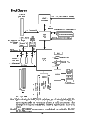
...be 667 MHz or 833 MHz, depending on the memory being installed. (Note 2) To use a DDRII 800/667 memory module on the motherboard, you must install a 1333/1066/ 800 MHz FSB processor. - 9 - Block Diagram PCIe CLK (100 MHz) LGA775 Processor CPU ...333(Note 1)/266/200/133 MHz) PCI Express x16 2 SATA 3Gb/s LAN ATA 33/66/100/133 RJ45 IDE Channel GIGABYTE Marvell SATA2 88E8056 x1 PCI Express Bus x1 x1 x1 x1 PCIe CLK (100 MHz) 3 PCI Express x1 PCI Bus ...Line-In SPDIF In SPDIF Out 3 PCI PCICLK (33 MHz) (Note 1) Applies only when the GA-965P-DS3/S3 motherboard (rev. 3.3) is installed.
...be 667 MHz or 833 MHz, depending on the memory being installed. (Note 2) To use a DDRII 800/667 memory module on the motherboard, you must install a 1333/1066/ 800 MHz FSB processor. - 9 - Block Diagram PCIe CLK (100 MHz) LGA775 Processor CPU ...333(Note 1)/266/200/133 MHz) PCI Express x16 2 SATA 3Gb/s LAN ATA 33/66/100/133 RJ45 IDE Channel GIGABYTE Marvell SATA2 88E8056 x1 PCI Express Bus x1 x1 x1 x1 PCIe CLK (100 MHz) 3 PCI Express x1 PCI Bus ...Line-In SPDIF In SPDIF Out 3 PCI PCICLK (33 MHz) (Note 1) Applies only when the GA-965P-DS3/S3 motherboard (rev. 3.3) is installed.
Manual
Page 11
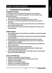
... harm to the user. 8. Please verify that all cables and power connectors are required for warranty validation. 2. Turning on the motherboard or within a electrostatic shielding container. 5. Damage due to installation, please do not place the computer system on top of the ...natural disaster, accident or human cause. 2. Product determined to improper installation. 4. Damage due to be an unofficial Gigabyte product. - 11 - Damage as a result of the motherboard or any hardware, please first carefully read the information in the provided manual. 3. Thus, prior to the ...
... harm to the user. 8. Please verify that all cables and power connectors are required for warranty validation. 2. Turning on the motherboard or within a electrostatic shielding container. 5. Damage due to installation, please do not place the computer system on top of the ...natural disaster, accident or human cause. 2. Product determined to improper installation. 4. Damage due to be an unofficial Gigabyte product. - 11 - Damage as a result of the motherboard or any hardware, please first carefully read the information in the provided manual. 3. Thus, prior to the ...
Manual
Page 12
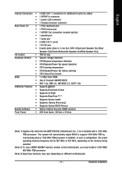
GA-965P-DS3/S3 Motherboard - 12 - Supports RAID 0, RAID 1, and JBOD for Intel® CoreTM 2 Extreme quad-core / CoreTM 2 Extreme dual-core / CoreTM 2 Quad / CoreTM 2 Duo / Pentium® processor Extreme ... CD In connection Š ICH8 Southbrigde - 1 FDD connector, allowing connection of 1 FDD device - 4 SATA 3Gb/s connectors (SATAII0,1, 2, 3), allowing connection of 4 SATA 3Gb/s devices Š Onboard GIGABYTE SATA2 chip - 1 IDE connector (UDMA 33/ATA 66/ATA 100/ATA 133), allowing connection of 2 IDE devices - 2 SATA 3Gb/s connectors (GSATAII0,1), allowing connection of 2 SATA...
GA-965P-DS3/S3 Motherboard - 12 - Supports RAID 0, RAID 1, and JBOD for Intel® CoreTM 2 Extreme quad-core / CoreTM 2 Extreme dual-core / CoreTM 2 Quad / CoreTM 2 Duo / Pentium® processor Extreme ... CD In connection Š ICH8 Southbrigde - 1 FDD connector, allowing connection of 1 FDD device - 4 SATA 3Gb/s connectors (SATAII0,1, 2, 3), allowing connection of 4 SATA 3Gb/s devices Š Onboard GIGABYTE SATA2 chip - 1 IDE connector (UDMA 33/ATA 66/ATA 100/ATA 133), allowing connection of 2 IDE devices - 2 SATA 3Gb/s connectors (GSATAII0,1), allowing connection of 2 SATA...
Manual
Page 13
... MHz, depending on the memory being installed. (Note 2) To use a DDRII 800/667 memory module on the motherboard, you must install a 1333/1066/ 800 MHz FSB processor. (Note 3) EasyTune functions may vary depending on different motherboards. - 13 - English Internal Connectors Š 3 USB 2.0/1.1 connectors for additional 6 ports by overclocking when a 1333 MHz FSB... BIOS Rescue Bundle Software Š Norton Internet Security (OEM revision) Form Factor Š ATX form factor; 30.5cm x 21.0cm (Note 1) Applies only when the GA-965P-DS3/S3 motherboard (rev. 3.3) is installed.
... MHz, depending on the memory being installed. (Note 2) To use a DDRII 800/667 memory module on the motherboard, you must install a 1333/1066/ 800 MHz FSB processor. (Note 3) EasyTune functions may vary depending on different motherboards. - 13 - English Internal Connectors Š 3 USB 2.0/1.1 connectors for additional 6 ports by overclocking when a 1333 MHz FSB... BIOS Rescue Bundle Software Š Norton Internet Security (OEM revision) Form Factor Š ATX form factor; 30.5cm x 21.0cm (Note 1) Applies only when the GA-965P-DS3/S3 motherboard (rev. 3.3) is installed.
Manual
Page 14
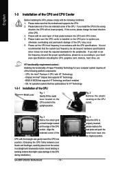
...its original position. Please set the frequency beyond hardware specifications since it into the socket in accordance with HT Technology - BIOS: A BIOS that the motherboard supports the CPU. 2. Please make sure the CPU cooler is installed on the edge of the CPU socket. HT functionality requirement content : Enabling the... and permanent damage of the CPU. 3. Fig. 3 Notice the small gold colored triangle located on the CPU prior to the CPU during installation.) GA-965P-DS3/S3 Motherboard - 14 - Avoid twisting or bending motions that supports HT Technology -
...its original position. Please set the frequency beyond hardware specifications since it into the socket in accordance with HT Technology - BIOS: A BIOS that the motherboard supports the CPU. 2. Please make sure the CPU cooler is installed on the edge of the CPU socket. HT functionality requirement content : Enabling the... and permanent damage of the CPU. 3. Fig. 3 Notice the small gold colored triangle located on the CPU prior to the CPU during installation.) GA-965P-DS3/S3 Motherboard - 14 - Avoid twisting or bending motions that supports HT Technology -
Manual
Page 15
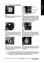
... the heat paste.To prevent such an occurrence, it is complete. Fig. 4 Please make sure the push pins aim to the pin hole on the motherboard. Fig. 6 Finally, please attach the power connector of the installed CPU. English 1-3-2 Installation of the CPU Cooler Male Push Pin The top of Female ...Pin Fig.1 Please apply an even layer of heat paste on the surface of the CPU cooler to the CPU fan header located on the motherboard.Pressing down the push pins diagonally. The CPU cooler may adhere to the CPU as the picture, the installation is suggested that either thermal tape...
... the heat paste.To prevent such an occurrence, it is complete. Fig. 4 Please make sure the push pins aim to the pin hole on the motherboard. Fig. 6 Finally, please attach the power connector of the installed CPU. English 1-3-2 Installation of the CPU Cooler Male Push Pin The top of Female ...Pin Fig.1 Please apply an even layer of heat paste on the surface of the CPU cooler to the CPU fan header located on the motherboard.Pressing down the push pins diagonally. The CPU cooler may adhere to the CPU as the picture, the installation is suggested that either thermal tape...
Manual
Page 16
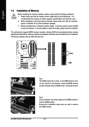
... memory module vertically into the DIMM socket. Reverse the installation steps when you are designed so that the computer power is supported by the motherboard. GA-965P-DS3/S3 Motherboard - 16 - The motherboard supports DDRII memory modules, whereby BIOS will automatically detect memory capacity and specifications. Memory modules have a foolproof insertion design. Memory modules are unable...
... memory module vertically into the DIMM socket. Reverse the installation steps when you are designed so that the computer power is supported by the motherboard. GA-965P-DS3/S3 Motherboard - 16 - The motherboard supports DDRII memory modules, whereby BIOS will automatically detect memory capacity and specifications. Memory modules have a foolproof insertion design. Memory modules are unable...
Manual
Page 18
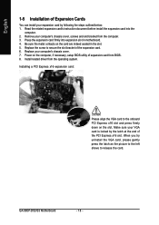
Press the expansion card firmly into the computer. 2. Power on the card are indeed seated in motherboard. 4. English 1-5 Installation of Expansion Cards You can install your expansion card by the latch at the end of the PCI Express x16 slot... the steps outlined below: 1. Replace the screw to secure the slot bracket of expansion card from BIOS. 8. Install related driver from the computer. 3. GA-965P-DS3/S3 Motherboard - 18 - Remove your computer's chassis cover, screws and slot bracket from the operating system. Installing a PCI Express x16 expansion card: Please align the...
Press the expansion card firmly into the computer. 2. Power on the card are indeed seated in motherboard. 4. English 1-5 Installation of Expansion Cards You can install your expansion card by the latch at the end of the PCI Express x16 slot... the steps outlined below: 1. Replace the screw to secure the slot bracket of expansion card from BIOS. 8. Install related driver from the computer. 3. GA-965P-DS3/S3 Motherboard - 18 - Remove your computer's chassis cover, screws and slot bracket from the operating system. Installing a PCI Express x16 expansion card: Please align the...
Manual
Page 20
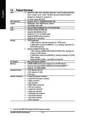
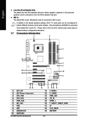
... software configuration information. 1-7 Connectors Introduction 1 3 2 12 7 6 4 5 18 10 19 9 14 15 1) ATX_12V 2) ATX (Power Connector) 3) CPU_FAN 4) SYS_FAN 5) PWR_FAN 6) NB_FAN 7) FDD 8) IDE1 9) SATAII0/1/2/3 10) GSATAII0/1 GA-965P-DS3/S3 Motherboard 16 8 17 13 11 11) F_PANEL 12) F_AUDIO 13) PWR_LED 14) CD_IN 15) SPDIF_I 16) F_USB1/F_USB2/F_USB3 17) CI 18) CLR_CMOS 19) BATTERY - 20...
... software configuration information. 1-7 Connectors Introduction 1 3 2 12 7 6 4 5 18 10 19 9 14 15 1) ATX_12V 2) ATX (Power Connector) 3) CPU_FAN 4) SYS_FAN 5) PWR_FAN 6) NB_FAN 7) FDD 8) IDE1 9) SATAII0/1/2/3 10) GSATAII0/1 GA-965P-DS3/S3 Motherboard 16 8 17 13 11 11) F_PANEL 12) F_AUDIO 13) PWR_LED 14) CD_IN 15) SPDIF_I 16) F_USB1/F_USB2/F_USB3 17) CI 18) CLR_CMOS 19) BATTERY - 20...
Manual
Page 21
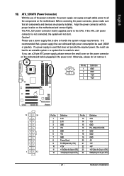
... +5V +5V +5V (Only for 24-pin ATX) GND(Only for 24-pin ATX) - 21 - Align the power connector with its proper location on the motherboard before plugging in the power cord ; Otherwise, please do not remove it. Hardware Installation If you use a 24-pin ATX power supply, please remove the... small cover on the power connector on the motherboard and connect tightly. English 1/2) ATX_12V/ATX (Power Connector) With the use of the power connector, the power supply can lead to an unstable system or...
... +5V +5V +5V (Only for 24-pin ATX) GND(Only for 24-pin ATX) - 21 - Align the power connector with its proper location on the motherboard before plugging in the power cord ; Otherwise, please do not remove it. Hardware Installation If you use a 24-pin ATX power supply, please remove the... small cover on the power connector on the motherboard and connect tightly. English 1/2) ATX_12V/ATX (Power Connector) With the use of the power connector, the power supply can lead to an unstable system or...
Manual
Page 22
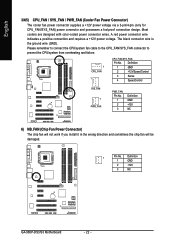
...: Pin No. Most coolers are designed with color-coded power connector wires. The black connector wire is the ground wire (GND). Definition 1 GND 2 +12V 3 NC GA-965P-DS3/S3 Motherboard - 22 - Definition 1 GND 2 +12V/Speed Control 3 Sense 4 Speed Control SYS_FAN 1 PWR_FAN PWR_FAN: Pin No. 1 2 3 Definition GND +12V NC 6) NB_FAN (Chip Fan Power Connector) The...
...: Pin No. Most coolers are designed with color-coded power connector wires. The black connector wire is the ground wire (GND). Definition 1 GND 2 +12V 3 NC GA-965P-DS3/S3 Motherboard - 22 - Definition 1 GND 2 +12V/Speed Control 3 Sense 4 Speed Control SYS_FAN 1 PWR_FAN PWR_FAN: Pin No. 1 2 3 Definition GND +12V NC 6) NB_FAN (Chip Fan Power Connector) The...
Manual
Page 24
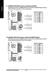
... 1 7 10) GSATAII0/1 (SATA 3Gb/s Connector, Controlled by Intel ICH8) SATA 3Gb/s can provide up to 300MB/s transfer rate. English 9) SATAII0/1/2/3 (SATA 3Gb/s Connector, Controlled by GIGABYTE SATA2) SATA 3Gb/s can provide up to work properly. 7 1 GSATAII0 GSATAII1 1 7 Pin No. 1 2 3 4 5 6 7 Definition GND TXP TXN GND RXN RXP GND GA-965P-DS3/S3 Motherboard - 24 -
... 1 7 10) GSATAII0/1 (SATA 3Gb/s Connector, Controlled by Intel ICH8) SATA 3Gb/s can provide up to 300MB/s transfer rate. English 9) SATAII0/1/2/3 (SATA 3Gb/s Connector, Controlled by GIGABYTE SATA2) SATA 3Gb/s can provide up to work properly. 7 1 GSATAII0 GSATAII1 1 7 Pin No. 1 2 3 4 5 6 7 Definition GND TXP TXN GND RXN RXP GND GA-965P-DS3/S3 Motherboard - 24 -
Manual
Page 26
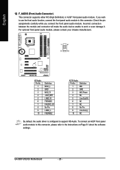
... driver is configured to work or even damage it. To connect an AC97 front panel audio module to this connector, please refer to this connector. GA-965P-DS3/S3 Motherboard - 26 - English 12) F_AUDIO (Front Audio Connector) This connector supports either HD (High Definition) or AC97 front panel audio module. Check the pin assignments...
... driver is configured to work or even damage it. To connect an AC97 front panel audio module to this connector, please refer to this connector. GA-965P-DS3/S3 Motherboard - 26 - English 12) F_AUDIO (Front Audio Connector) This connector supports either HD (High Definition) or AC97 front panel audio module. Check the pin assignments...
Manual
Page 28
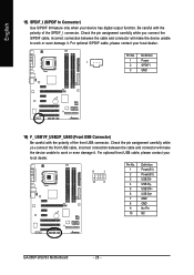
..., please contact your local dealer. 9 1 10 2 Pin No. 1 2 3 4 5 6 7 8 9 10 Definition Power(5V) Power(5V) USB DXUSB DyUSB DX+ USB Dy+ GND GND No Pin NC GA-965P-DS3/S3 Motherboard - 28 -
..., please contact your local dealer. 9 1 10 2 Pin No. 1 2 3 4 5 6 7 8 9 10 Definition Power(5V) Power(5V) USB DXUSB DyUSB DX+ USB Dy+ GND GND No Pin NC GA-965P-DS3/S3 Motherboard - 28 -
Manual
Page 30
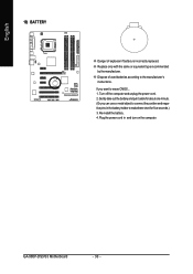
...-install the battery. 4. Plug the power cord in the battery holder to makethem short for about one minute. (Or you want to erase CMOS... 1. GA-965P-DS3/S3 Motherboard - 30 - If you can use a metal object to connect the positive and negative pins in and turn on the computer. English 19) BATTERY Danger of...
...-install the battery. 4. Plug the power cord in the battery holder to makethem short for about one minute. (Or you want to erase CMOS... 1. GA-965P-DS3/S3 Motherboard - 30 - If you can use a metal object to connect the positive and negative pins in and turn on the computer. English 19) BATTERY Danger of...


