Manual
Page 5
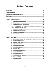
... 1-2 Feature Summary 12 1-3 Installation of the CPU and CPU Cooler 14 1-3-1 Installation of the CPU 14 1-3-2 Installation of the CPU Cooler 15 1-4 Installation of Memory 16 1-5 Installation of Expansion Cards 18 1-6 I/O Back Panel Introduction 19 1-7 Connectors Introduction 20 Chapter 2 BIOS Setup 31 The Main Menu (Example BIOS Ver.: GA-965P-DS3, F10a 32 2-1 Standard CMOS Features 34...
... 1-2 Feature Summary 12 1-3 Installation of the CPU and CPU Cooler 14 1-3-1 Installation of the CPU 14 1-3-2 Installation of the CPU Cooler 15 1-4 Installation of Memory 16 1-5 Installation of Expansion Cards 18 1-6 I/O Back Panel Introduction 19 1-7 Connectors Introduction 20 Chapter 2 BIOS Setup 31 The Main Menu (Example BIOS Ver.: GA-965P-DS3, F10a 32 2-1 Standard CMOS Features 34...
Manual
Page 9
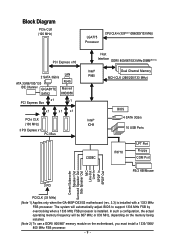
... installed with a 1333 MHz FSB processor. Block Diagram PCIe CLK (100 MHz) LGA775 Processor CPU CLK+/-(333(Note 1)/266/200/133 MHz) PCI Express x16 2 SATA 3Gb/s LAN ATA 33/66/100/133 RJ45 IDE Channel GIGABYTE Marvell SATA2 88E8056 x1 PCI Express Bus x1 x1 x1 x1 PCIe CLK (100 MHz... Out Surround Speaker Out Side Speaker Out MIC Line-Out Line-In SPDIF In SPDIF Out 3 PCI PCICLK (33 MHz) (Note 1) Applies only when the GA-965P-DS3/S3 motherboard (rev. 3.3) is installed.
... installed with a 1333 MHz FSB processor. Block Diagram PCIe CLK (100 MHz) LGA775 Processor CPU CLK+/-(333(Note 1)/266/200/133 MHz) PCI Express x16 2 SATA 3Gb/s LAN ATA 33/66/100/133 RJ45 IDE Channel GIGABYTE Marvell SATA2 88E8056 x1 PCI Express Bus x1 x1 x1 x1 PCIe CLK (100 MHz... Out Surround Speaker Out Side Speaker Out MIC Line-Out Line-In SPDIF In SPDIF Out 3 PCI PCICLK (33 MHz) (Note 1) Applies only when the GA-965P-DS3/S3 motherboard (rev. 3.3) is installed.
Manual
Page 11
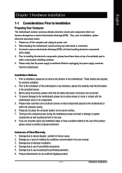
...Before using the product, please verify that the power supply is best to wear an electrostatic discharge (ESD) cuff when handling electronic components (CPU, RAM). 4. Prior to installing the electronic components, please have a problem related to the use of Non-Warranty 1. Prior to the... pad or within the computer casing. 6. Please make sure there are required for warranty validation. 2. Damage due to be an unofficial Gigabyte product. - 11 - Damage due to use of electrostatic discharge (ESD). When handling the motherboard, avoid touching any hardware, please first...
...Before using the product, please verify that the power supply is best to wear an electrostatic discharge (ESD) cuff when handling electronic components (CPU, RAM). 4. Prior to installing the electronic components, please have a problem related to the use of Non-Warranty 1. Prior to the... pad or within the computer casing. 6. Please make sure there are required for warranty validation. 2. Damage due to be an unofficial Gigabyte product. - 11 - Damage due to use of electrostatic discharge (ESD). When handling the motherboard, avoid touching any hardware, please first...
Manual
Page 12
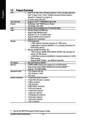
...,1, 2, 3), allowing connection of 4 SATA 3Gb/s devices Š Onboard GIGABYTE SATA2 chip - 1 IDE connector (UDMA 33/ATA 66/ATA 100/ATA 133), allowing connection of 2 IDE devices - 2 SATA 3Gb/s connectors (GSATAII0,1), allowing connection of 2 SATA 3Gb/s devices - GA-965P-DS3/S3 Motherboard - 12 - English 1-2 Feature Summary CPU Š LGA775 for Serial ATA O.S Support Š Microsoft Windows...
...,1, 2, 3), allowing connection of 4 SATA 3Gb/s devices Š Onboard GIGABYTE SATA2 chip - 1 IDE connector (UDMA 33/ATA 66/ATA 100/ATA 133), allowing connection of 2 IDE devices - 2 SATA 3Gb/s connectors (GSATAII0,1), allowing connection of 2 SATA 3Gb/s devices - GA-965P-DS3/S3 Motherboard - 12 - English 1-2 Feature Summary CPU Š LGA775 for Serial ATA O.S Support Š Microsoft Windows...
Manual
Page 13
... Control Š IT8718 chip Hardware Monitor Š System voltage detection Š CPU/System temperature detection Š CPU/System/Power fan speed detection Š CPU warning temperature Š CPU/System/Power fan failure warning Š CPU Smart Fan Control BIOS Š 1 8 Mbit flash ROM Š Use of... Norton Internet Security (OEM revision) Form Factor Š ATX form factor; 30.5cm x 21.0cm (Note 1) Applies only when the GA-965P-DS3/S3 motherboard (rev. 3.3) is installed. Hardware Installation The system will be 667 MHz or 833 MHz, depending on the memory being installed...
... Control Š IT8718 chip Hardware Monitor Š System voltage detection Š CPU/System temperature detection Š CPU/System/Power fan speed detection Š CPU warning temperature Š CPU/System/Power fan failure warning Š CPU Smart Fan Control BIOS Š 1 8 Mbit flash ROM Š Use of... Norton Internet Security (OEM revision) Form Factor Š ATX form factor; 30.5cm x 21.0cm (Note 1) Applies only when the GA-965P-DS3/S3 motherboard (rev. 3.3) is installed. Hardware Installation The system will be 667 MHz or 833 MHz, depending on the memory being installed...
Manual
Page 14
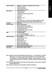
... the peripherals. Please set beyond the proper specifications, please do so according to the CPU during installation.) GA-965P-DS3/S3 Motherboard - 14 - BIOS: A BIOS that the motherboard supports the CPU. 2. Fig. 3 Notice the small gold colored triangle located on the CPU prior to the upright position. Please make sure that supports HT Technology and has...
... the peripherals. Please set beyond the proper specifications, please do so according to the CPU during installation.) GA-965P-DS3/S3 Motherboard - 14 - BIOS: A BIOS that the motherboard supports the CPU. 2. Fig. 3 Notice the small gold colored triangle located on the CPU prior to the upright position. Please make sure that supports HT Technology and has...
Manual
Page 15
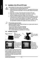
... pin is inserted as a result of hardening of the heat paste.To prevent such an occurrence, it is complete. Hardware Installation English 1-3-2 Installation of the CPU Cooler Male Push Pin The top of Female Push Pin Female Push Pin Fig.1 Please apply an even layer of heat paste on the motherboard.... Fig. 4 Please make sure the Male and Female push pin are joined closely. (for Intel boxed fan) Fig. 3 Place the CPU cooler atop the CPU and make sure the push pins aim to the pin hole on the male push pin doesn't face inwards before installation. (This instruction is...
... pin is inserted as a result of hardening of the heat paste.To prevent such an occurrence, it is complete. Hardware Installation English 1-3-2 Installation of the CPU Cooler Male Push Pin The top of Female Push Pin Female Push Pin Fig.1 Please apply an even layer of heat paste on the motherboard.... Fig. 4 Please make sure the Male and Female push pin are joined closely. (for Intel boxed fan) Fig. 3 Place the CPU cooler atop the CPU and make sure the push pins aim to the pin hole on the male push pin doesn't face inwards before installation. (This instruction is...
Manual
Page 21
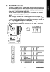
... (Only for 24-pin ATX) GND(Only for 24-pin ATX) - 21 - Before connecting the power connector, please make sure that is able to the CPU. Please use a power supply that does not provide the required power, the result can withstand high power consumption be used (300W or greater). English 1/2) ATX_12V...
... (Only for 24-pin ATX) GND(Only for 24-pin ATX) - 21 - Before connecting the power connector, please make sure that is able to the CPU. Please use a power supply that does not provide the required power, the result can withstand high power consumption be used (300W or greater). English 1/2) ATX_12V...
Manual
Page 22
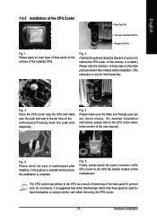
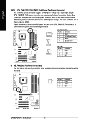
... fan cable to the CPU_FAN/SYS_FAN connector to prevent the CPU/system from overheating and failure. 1 CPU_FAN 1 CPU_FAN/SYS_FAN: Pin No. English 3/4/5) CPU_FAN / SYS_FAN / PWR_FAN (Cooler Fan Power Connector) The cooler fan ... A red power connector wire indicates a positive connection and requires a +12V power voltage. The black connector wire is the ground wire (GND). Definition 1 GND 2 +12V 3 NC GA-965P-DS3/S3 Motherboard - 22 - Definition 1 GND 2 +12V/Speed Control 3 Sense 4 Speed Control SYS_FAN 1 PWR_FAN PWR_FAN: Pin No. 1 2 3 Definition GND +12V NC 6) NB_FAN...
... fan cable to the CPU_FAN/SYS_FAN connector to prevent the CPU/system from overheating and failure. 1 CPU_FAN 1 CPU_FAN/SYS_FAN: Pin No. English 3/4/5) CPU_FAN / SYS_FAN / PWR_FAN (Cooler Fan Power Connector) The cooler fan ... A red power connector wire indicates a positive connection and requires a +12V power voltage. The black connector wire is the ground wire (GND). Definition 1 GND 2 +12V 3 NC GA-965P-DS3/S3 Motherboard - 22 - Definition 1 GND 2 +12V/Speed Control 3 Sense 4 Speed Control SYS_FAN 1 PWR_FAN PWR_FAN: Pin No. 1 2 3 Definition GND +12V NC 6) NB_FAN...
Manual
Page 33
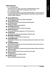
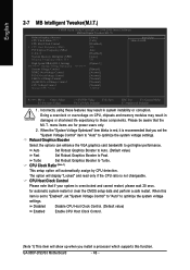
.... „ PC Health Status This setup page is the System auto detect Temperature, voltage, fan, speed. „ MB Intelligent Tweaker(M.I.T.) This setup page is control CPU clock and frequency ratio. „ Load Fail-Safe Defaults Fail-Safe Defaults indicates the value of the system parameters which the system would be in...
.... „ PC Health Status This setup page is the System auto detect Temperature, voltage, fan, speed. „ MB Intelligent Tweaker(M.I.T.) This setup page is control CPU clock and frequency ratio. „ Load Fail-Safe Defaults Fail-Safe Defaults indicates the value of the system parameters which the system would be in...
Manual
Page 35
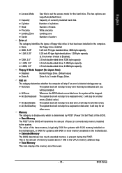
... for all other errors. The value of currently installed hard disk. Total Memory This item displays the memory size that has been installed in the CPU's memory address map. The two options are: Large/Auto(default:Auto) Capacity Capacity of the base memory is typically 512K for systems with 640K or...
... for all other errors. The value of currently installed hard disk. Total Memory This item displays the memory size that has been installed in the CPU's memory address map. The two options are: Large/Auto(default:Auto) Capacity Capacity of the base memory is typically 512K for systems with 640K or...
Manual
Page 36
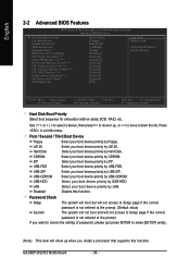
... Check Setup The system will boot but will not access to 3 (Note) No-Execute Memory Protect (Note) CPU Enhanced Halt (C1E)(Note) CPU Thermal Monitor 2(TM2) (Note) CPU EIST Function (Note) Virtualization Technology(Note) Full Screen LOGO Show Init Display First [Press Enter] [Floppy] [...device, then press to move it down the list. First / Second / Third Boot Device Floppy Select your boot device priority by Floppy. GA-965P-DS3/S3 Motherboard - 36 - English 2-2 Advanced BIOS Features CMOS Setup Utility-Copyright (C) 1984-2006 Award Software Advanced BIOS Features Hard Disk Boot ...
... Check Setup The system will boot but will not access to 3 (Note) No-Execute Memory Protect (Note) CPU Enhanced Halt (C1E)(Note) CPU Thermal Monitor 2(TM2) (Note) CPU EIST Function (Note) Virtualization Technology(Note) Full Screen LOGO Show Init Display First [Press Enter] [Floppy] [...device, then press to move it down the list. First / Second / Third Boot Device Floppy Select your boot device priority by Floppy. GA-965P-DS3/S3 Motherboard - 36 - English 2-2 Advanced BIOS Features CMOS Setup Utility-Copyright (C) 1984-2006 Award Software Advanced BIOS Features Hard Disk Boot ...
Manual
Page 37
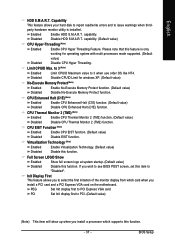
... full screen logo at system startup. (Default value) Disable this function. capability. CPU Enhanced Halt (C1E) (Note) Enabled Disabled Enable CPU Enhanced Halt (C1E) function. (Default value) Disable CPU Enhanced Halt (C1E) function. Init Display First This feature allows you to see ... This feature allows your hard disk to report read/write errors and to "Disabled". capability. (Default value) CPU Hyper-Threading (Note) Enabled Enable CPU Hyper Threading Feature. BIOS Setup Please note that this item to issue warnings when thirdparty hardware monitor utility is ...
... full screen logo at system startup. (Default value) Disable this function. capability. CPU Enhanced Halt (C1E) (Note) Enabled Disabled Enable CPU Enhanced Halt (C1E) function. (Default value) Disable CPU Enhanced Halt (C1E) function. Init Display First This feature allows you to see ... This feature allows your hard disk to report read/write errors and to "Disabled". capability. (Default value) CPU Hyper-Threading (Note) Enabled Enable CPU Hyper Threading Feature. BIOS Setup Please note that this item to issue warnings when thirdparty hardware monitor utility is ...
Manual
Page 44
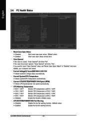
..." value, set "Reset Case Open Status" to "Enabled" and save CMOS, your computer will restart. CPU Warning Temperature 60oC / 140oF Monitor CPU temperature at 60oC / 140oF. 70oC / 158oF 80oC / 176oF 90oC / 194oF Monitor CPU temperature at 80oC / 176oF. GA-965P-DS3/S3 Motherboard - 44 - Current Voltage(V) Vcore/DDR18V/+3.3V/+12V Detect system's voltage status automatically. Monitor...
..." value, set "Reset Case Open Status" to "Enabled" and save CMOS, your computer will restart. CPU Warning Temperature 60oC / 140oF Monitor CPU temperature at 60oC / 140oF. 70oC / 158oF 80oC / 176oF 90oC / 194oF Monitor CPU temperature at 80oC / 176oF. GA-965P-DS3/S3 Motherboard - 44 - Current Voltage(V) Vcore/DDR18V/+3.3V/+12V Detect system's voltage status automatically. Monitor...
Manual
Page 45
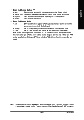
...to Intel(R) QST, make sure at full speed. PWM Set to Voltage when you use a CPU fan with a 3-pin fan power cable. English Smart FAN Control Method (Note) Auto BIOS sets the optimal CPU fan speed automatically. (Default value) Intel(R) QST Control the fan speed with 3-pin or 4-...pin power cables. With such CPU fans, selecting PWM will be used for it. (Default value) Voltage Set to PWM...
...to Intel(R) QST, make sure at full speed. PWM Set to Voltage when you use a CPU fan with a 3-pin fan power cable. English Smart FAN Control Method (Note) Auto BIOS sets the optimal CPU fan speed automatically. (Default value) Intel(R) QST Control the fan speed with 3-pin or 4-...pin power cables. With such CPU fans, selecting PWM will be used for it. (Default value) Voltage Set to PWM...
Manual
Page 46
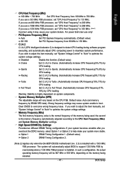
... CPU ratio is overclocked and cannot restart, please wait 20 secs. GA-965P-DS3/S3 Motherboard - 46 - Disabled Disable CPU Host Clock Control. (Default value) Enabled Enable CPU Host Clock Control. (Note 1) This item will automatically assign by CPU detection. CPU ...Speed DRAM DLL Settings ******** System Voltage Optimized System Voltage Control DDR2 OverVoltage Control PCI-E OverVoltage Control FSB OverVoltage Control (G)MCH OverVoltage Control CPU Voltage Control Normal CPU Vcore ******** [Auto] [16X] [Disabled] 200 Auto [Disabled] [Auto] 533 [Option 1] [Manual] [Normal] [Normal]...
... CPU ratio is overclocked and cannot restart, please wait 20 secs. GA-965P-DS3/S3 Motherboard - 46 - Disabled Disable CPU Host Clock Control. (Default value) Enabled Enable CPU Host Clock Control. (Note 1) This item will automatically assign by CPU detection. CPU ...Speed DRAM DLL Settings ******** System Voltage Optimized System Voltage Control DDR2 OverVoltage Control PCI-E OverVoltage Control FSB OverVoltage Control (G)MCH OverVoltage Control CPU Voltage Control Normal CPU Vcore ******** [Auto] [16X] [Disabled] 200 Auto [Disabled] [Auto] 533 [Option 1] [Manual] [Normal] [Normal]...
Manual
Page 47
...Configuration 2. (Note 2) Applies only when the GA-965P-DS3/S3 motherboard (rev. 3.3) is the memory frequency automatically adjusted according to Cruise. (Automatically increase CPU frequency(5%,7%) by CPU loading. If you wish to adjust the item manually, set "CPU Host Frequency" to optimize the system voltage settings...Incorrect using it may cause system unable to Full Thrust. (Automatically increase CPU frequency(17%, 19%) by CPU loading. BIOS Setup English CPU Host Frequency (Mhz) 100 MHz ~ 700 MHz Set CPU Host Frequency from 90 MHz to 133 MHz. If you use only!...
...Configuration 2. (Note 2) Applies only when the GA-965P-DS3/S3 motherboard (rev. 3.3) is the memory frequency automatically adjusted according to Cruise. (Automatically increase CPU frequency(5%,7%) by CPU loading. If you wish to adjust the item manually, set "CPU Host Frequency" to optimize the system voltage settings...Incorrect using it may cause system unable to Full Thrust. (Automatically increase CPU frequency(17%, 19%) by CPU loading. BIOS Setup English CPU Host Frequency (Mhz) 100 MHz ~ 700 MHz Set CPU Host Frequency from 90 MHz to 133 MHz. If you use only!...
Manual
Page 48
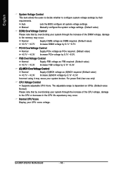
... PCIe required. (Default value) +0.1V ~ +0.3V Increase PCIe voltage by 0.1V ~0.3V. For power End-User use only! GA-965P-DS3/S3 Motherboard - 48 - English System Voltage Control This item allows the users to decide whether to the memory may occur. Manual Manually ... value: Normal) Please note that by overclocking your system through the increase of the CPU voltage, damage to the CPU or decrease in the CPU life expectancy may cause your CPU vcore voltage. Normal CPU Vcore Display your system broken. Normal Supply DIMM voltage as (G)MCH required. (Default ...
... PCIe required. (Default value) +0.1V ~ +0.3V Increase PCIe voltage by 0.1V ~0.3V. For power End-User use only! GA-965P-DS3/S3 Motherboard - 48 - English System Voltage Control This item allows the users to decide whether to the memory may occur. Manual Manually ... value: Normal) Please note that by overclocking your system through the increase of the CPU voltage, damage to the CPU or decrease in the CPU life expectancy may cause your CPU vcore voltage. Normal CPU Vcore Display your system broken. Normal Supply DIMM voltage as (G)MCH required. (Default ...
Manual
Page 57
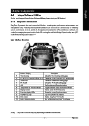
...between Easy and Advance Mode 7. GIGABYTE Logo Log on different motherboards. - 57 - for special enhancement for CPU and Memory, 3) Smart-Fan control for managing fan speed control of CPU frequency 8. Display screen Display panel of both CPU cooling fan and North-Bridge Chipset ... 1) Overclocking for monitoring system status.(Note) User Interface Overview Button / Display Description 1. Featuring several powerful yet easy to GIGABYTE website 10. English Chapter 4 Appendix 4-1 Unique Software Utilities (Not all model support these Unique Software Utilities, please check ...
...between Easy and Advance Mode 7. GIGABYTE Logo Log on different motherboards. - 57 - for special enhancement for CPU and Memory, 3) Smart-Fan control for managing fan speed control of CPU frequency 8. Display screen Display panel of both CPU cooling fan and North-Bridge Chipset ... 1) Overclocking for monitoring system status.(Note) User Interface Overview Button / Display Description 1. Featuring several powerful yet easy to GIGABYTE website 10. English Chapter 4 Appendix 4-1 Unique Software Utilities (Not all model support these Unique Software Utilities, please check ...
Manual
Page 66
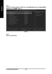
Capability CPU Hyper-Threading Limit CPUID Max. CMOS Setup Utility-Copyright (C) 1984-2006 Award Software Advanced BIOS Features...from Windows installation CD-ROM disk, set First Boot Device under the Advanced BIOS Features menu to 3 No-Execute Memory Protect CPU Enhanced Halt (C1E) CPU Thermal Monitor 2(TM2) CPU EIST Function Virtualization Technology Full Screen LOGO Show Init Display First [Press Enter] [CDROM] [Hard Disk] [CDROM] [Setup...PU/PD: Value F10: Save F6: Fail-Safe Defaults Figure 2 ESC: Exit F1: General Help F7: Optimized Defaults GA-965P-DS3/S3 Motherboard - 66 -
Capability CPU Hyper-Threading Limit CPUID Max. CMOS Setup Utility-Copyright (C) 1984-2006 Award Software Advanced BIOS Features...from Windows installation CD-ROM disk, set First Boot Device under the Advanced BIOS Features menu to 3 No-Execute Memory Protect CPU Enhanced Halt (C1E) CPU Thermal Monitor 2(TM2) CPU EIST Function Virtualization Technology Full Screen LOGO Show Init Display First [Press Enter] [CDROM] [Hard Disk] [CDROM] [Setup...PU/PD: Value F10: Save F6: Fail-Safe Defaults Figure 2 ESC: Exit F1: General Help F7: Optimized Defaults GA-965P-DS3/S3 Motherboard - 66 -


