
User Manual
Page 1
GA-8VM800M Intel® Pentium® 4 Processor Motherboard User's Manual Rev. 1002 12ME-8VM800M-1002R * The WEEE marking on the product indicates this product must not be disposed of with user's other household waste and must be handed over to a designated collection point for the recycling of waste electrical and electronic equipment!! * The WEEE marking applies only in European Union's member states.
GA-8VM800M Intel® Pentium® 4 Processor Motherboard User's Manual Rev. 1002 12ME-8VM800M-1002R * The WEEE marking on the product indicates this product must not be disposed of with user's other household waste and must be handed over to a designated collection point for the recycling of waste electrical and electronic equipment!! * The WEEE marking applies only in European Union's member states.

User Manual
Page 2
Motherboard GA-8VM800M Nov. 28, 2005 Motherboard GA-8VM800M Nov. 28, 2005
Motherboard GA-8VM800M Nov. 28, 2005 Motherboard GA-8VM800M Nov. 28, 2005

User Manual
Page 4
Table of Contents GA-8VM800M Motherboard Layout 6 Block Diagram ...7 Chapter 1 Hardware Installation 9 1-1 Considerations Prior to Installation 9 1-2 Feature Summary 10 1-3 Installation of the CPU and Heatsink 12 1-3-1 Installation of the CPU ...
Table of Contents GA-8VM800M Motherboard Layout 6 Block Diagram ...7 Chapter 1 Hardware Installation 9 1-1 Considerations Prior to Installation 9 1-2 Feature Summary 10 1-3 Installation of the CPU and Heatsink 12 1-3-1 Installation of the CPU ...
User Manual
Page 10
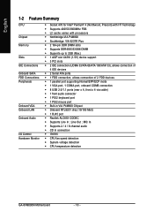
... ; MIC In Š Supports 2 / 4 / 6 channel audio Š CD In connection Š IT8705 Š CPU fan speed detection Š System voltage detection Š CPU temperature detection GA-8VM800M Motherboard - 10 -
... ; MIC In Š Supports 2 / 4 / 6 channel audio Š CD In connection Š IT8705 Š CPU fan speed detection Š System voltage detection Š CPU temperature detection GA-8VM800M Motherboard - 10 -

User Manual
Page 12
... with the processor specifications. If you install the CPU in accordance with the socket edge closest to system use extra care when installing the CPU. GA-8VM800M Motherboard - 12 - It is marked one indented corner of the CPU Fig. 1 Socket lever Position lever at a 90 degree angle. The CPU will not insert...
... with the processor specifications. If you install the CPU in accordance with the socket edge closest to system use extra care when installing the CPU. GA-8VM800M Motherboard - 12 - It is marked one indented corner of the CPU Fig. 1 Socket lever Position lever at a 90 degree angle. The CPU will not insert...

User Manual
Page 14
... memory module Fig.2 Close the plastic clip at both edges of Memory Before installing the memory modules, please comply with the following conditions: 1. Fig. 1 Fig. 2 GA-8VM800M Motherboard - 14 -
... memory module Fig.2 Close the plastic clip at both edges of Memory Before installing the memory modules, please comply with the following conditions: 1. Fig. 1 Fig. 2 GA-8VM800M Motherboard - 14 -

User Manual
Page 16
... lower port (purple). For more information please contact your OS does not support USB controller, please contact OS vendor for possible patch or driver upgrade. GA-8VM800M Motherboard - 16 - VGA Port Monitor can be connected to MIC In jack. Serial Port (COMA) Devices like CD-ROM, walkman etc. English 1-6 I/O Back Panel Introduction...
... lower port (purple). For more information please contact your OS does not support USB controller, please contact OS vendor for possible patch or driver upgrade. GA-8VM800M Motherboard - 16 - VGA Port Monitor can be connected to MIC In jack. Serial Port (COMA) Devices like CD-ROM, walkman etc. English 1-6 I/O Back Panel Introduction...

User Manual
Page 18
... system voltage requirements. Align the power connector with its proper location on /off) 15 GND 16 GND 17 GND 18 -5V 19 +5V 20 +5V GA-8VM800M Motherboard - 18 - Pin No. Definition 1 3.3V 2 3.3V 3 GND 4 +5V 5 GND 6 +5V 7 GND 8 Power Good 9 5V SB (stand by +5V) 20 10 10 +12V 11 3.3V...
... system voltage requirements. Align the power connector with its proper location on /off) 15 GND 16 GND 17 GND 18 -5V 19 +5V 20 +5V GA-8VM800M Motherboard - 18 - Pin No. Definition 1 3.3V 2 3.3V 3 GND 4 +5V 5 GND 6 +5V 7 GND 8 Power Good 9 5V SB (stand by +5V) 20 10 10 +12V 11 3.3V...
User Manual
Page 20
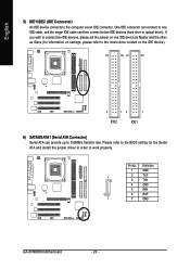
... instructions located on one IDE cable, and the single IDE cable can provide up to work properly. Definition 1 GND 2 TXP 1 3 TXN 4 GND 5 RXN 6 RXP 7 7 GND GA-8VM800M Motherboard - 20 -
... instructions located on one IDE cable, and the single IDE cable can provide up to work properly. Definition 1 GND 2 TXP 1 3 TXN 4 GND 5 RXN 6 RXP 7 7 GND GA-8VM800M Motherboard - 20 -
User Manual
Page 22
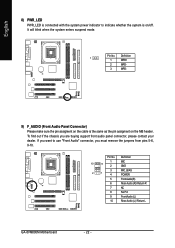
... must remove the jumpers from pins 5-6, 9-10. Definition 1 MIC 10 9 2 GND 3 2 1 4 MIC_BIAS POWER 5 FrontAudio(R) 6 Rear Audio (R)/ Return R 7 NC 8 No Pin 9 FrontAudio (L) 10 Rear Audio (L)/ Return L GA-8VM800M Motherboard - 22 - Definition 1 1 MPD+ 2 MPD- 3 MPD- 9) F_AUDIO (Front Audio Panel Connector) Please make sure the pin assigment on the cable is the same as the...
... must remove the jumpers from pins 5-6, 9-10. Definition 1 MIC 10 9 2 GND 3 2 1 4 MIC_BIAS POWER 5 FrontAudio(R) 6 Rear Audio (R)/ Return R 7 NC 8 No Pin 9 FrontAudio (L) 10 Rear Audio (L)/ Return L GA-8VM800M Motherboard - 22 - Definition 1 1 MPD+ 2 MPD- 3 MPD- 9) F_AUDIO (Front Audio Panel Connector) Please make sure the pin assigment on the cable is the same as the...

User Manual
Page 24
... (COMB Connector) Be careful with the polarity of the COMB connector. Definition 1 NDCDB- 2 10 2 NSINB 3 NSOUTB 1 9 4 NDTRB- 5 GND 6 NDSRB- 7 NRTSB- 8 NCTSB- 9 NRIB- 10 No Pin GA-8VM800M Motherboard - 24 - English 12) F_USB1 / F_USB2 (Front USB Connectors) Be careful with the polarity of the front USB connector. Check the pin assignments while you...
... (COMB Connector) Be careful with the polarity of the COMB connector. Definition 1 NDCDB- 2 10 2 NSINB 3 NSOUTB 1 9 4 NDTRB- 5 GND 6 NDSRB- 7 NRTSB- 8 NCTSB- 9 NRIB- 10 No Pin GA-8VM800M Motherboard - 24 - English 12) F_USB1 / F_USB2 (Front USB Connectors) Be careful with the polarity of the front USB connector. Check the pin assignments while you...

User Manual
Page 26
English GA-8VM800M Motherboard - 26 -
English GA-8VM800M Motherboard - 26 -
User Manual
Page 28
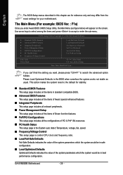
GA-8VM800M Motherboard - 28 - English The BIOS Setup menus described in best performance configuration. CMOS Setup Utility-Copyright (C) 1984-2005 Award Software ` Standard CMOS Features ` Advanced BIOS ...
GA-8VM800M Motherboard - 28 - English The BIOS Setup menus described in best performance configuration. CMOS Setup Utility-Copyright (C) 1984-2005 Award Software ` Standard CMOS Features ` Advanced BIOS ...

User Manual
Page 30
... detection step and allow for Japan Area) Disabled Drive A Normal Floppy Drive. (Default value) Drive A is 3 mode Floppy Drive. Extended IDE Drive SATA devices setup. GA-8VM800M Motherboard - 30 - Drive B Both Drive B is Enabled). 3.5 inch double-sided drive; 720K byte capacity 1.44M, 3.5" 3.5 inch double-sided drive; 1.44M byte capacity. 2.88M, 3.5" 3.5 inch double...
... detection step and allow for Japan Area) Disabled Drive A Normal Floppy Drive. (Default value) Drive A is 3 mode Floppy Drive. Extended IDE Drive SATA devices setup. GA-8VM800M Motherboard - 30 - Drive B Both Drive B is Enabled). 3.5 inch double-sided drive; 720K byte capacity 1.44M, 3.5" 3.5 inch double-sided drive; 1.44M byte capacity. 2.88M, 3.5" 3.5 inch double...

User Manual
Page 32
...-FDD Select your boot device priority by USB-FDD. CDROM Select your boot device priority by CDROM. ZIP Select your boot device priority by ZIP. GA-8VM800M Motherboard - 32 - English 2-2 Advanced BIOS Features CMOS Setup Utility-Copyright (C) 1984-2005 Award Software Advanced BIOS Features X Hard Disk Boot Priority First Boot Device Second...
...-FDD Select your boot device priority by USB-FDD. CDROM Select your boot device priority by CDROM. ZIP Select your boot device priority by ZIP. GA-8VM800M Motherboard - 32 - English 2-2 Advanced BIOS Features CMOS Setup Utility-Copyright (C) 1984-2005 Award Software Advanced BIOS Features X Hard Disk Boot Priority First Boot Device Second...

User Manual
Page 34
...-Chip LAN Boot ROM to RPL. Onboard Serial Port 2 Auto BIOS will automatically setup the port 1 address. Using Parallel port as ECP and EPP mode. GA-8VM800M Motherboard - 34 - VIA Onboard LAN English Enabled Enable VIA onboard LAN function. (Default value) Disabled Disable this function. (Default value) Onboard Serial Port 1 Auto 3F8...
...-Chip LAN Boot ROM to RPL. Onboard Serial Port 2 Auto BIOS will automatically setup the port 1 address. Using Parallel port as ECP and EPP mode. GA-8VM800M Motherboard - 34 - VIA Onboard LAN English Enabled Enable VIA onboard LAN function. (Default value) Disabled Disable this function. (Default value) Onboard Serial Port 1 Auto 3F8...

User Manual
Page 36
... "Resume by Alarm is Enabled. Disabled Disable Modem Ring Resume function. Date (of Month) Alarm : Everyday, 1~31 Time (hh: mm: ss) Alarm: (0~23) : (0~59) : (0~59) GA-8VM800M Motherboard - 36 - English Keyboard Power On Password Enter from any suspend state.
... "Resume by Alarm is Enabled. Disabled Disable Modem Ring Resume function. Date (of Month) Alarm : Everyday, 1~31 Time (hh: mm: ss) Alarm: (0~23) : (0~59) : (0~59) GA-8VM800M Motherboard - 36 - English Keyboard Power On Password Enter from any suspend state.

User Manual
Page 38
Current CPU FAN Speed (RPM) Detect CPU Fan speed status automatically. Current CPU Temperature Detect CPU temperature automatically. GA-8VM800M Motherboard - 38 - English 2-6 PC Health Status CMOS Setup Utility-Copyright (C) 1984-2005 Award Software PC Health Status Vcore DDR25V +3.3V +12V Current CPU Temperature Current ...
Current CPU FAN Speed (RPM) Detect CPU Fan speed status automatically. Current CPU Temperature Detect CPU temperature automatically. GA-8VM800M Motherboard - 38 - English 2-6 PC Health Status CMOS Setup Utility-Copyright (C) 1984-2005 Award Software PC Health Status Vcore DDR25V +3.3V +12V Current CPU Temperature Current ...

User Manual
Page 40
... only! If you use DDR333 DRAM module, please set "DRAM Clock" to +0.2V. If you use DDR400 DRAM module, please set "DRAM Clock" to "133". GA-8VM800M Motherboard - 40 - English DRAM Clock Please set DRAM Clock according to your requirement. (Default value: By SPD) If you use DDR266 DRAM module, please set...
... only! If you use DDR333 DRAM module, please set "DRAM Clock" to +0.2V. If you use DDR400 DRAM module, please set "DRAM Clock" to "133". GA-8VM800M Motherboard - 40 - English DRAM Clock Please set DRAM Clock according to your requirement. (Default value: By SPD) If you use DDR266 DRAM module, please set...
User Manual
Page 42
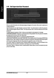
.... To disable password, just press when you can enter Setup freely. When disabled, anyone may also press to abort the selection and not enter a password. GA-8VM800M Motherboard - 42 - You may access all BIOS Setup program function. If you select "Setup" at "Password Check" in Advance BIOS Features Menu, you will be...
.... To disable password, just press when you can enter Setup freely. When disabled, anyone may also press to abort the selection and not enter a password. GA-8VM800M Motherboard - 42 - You may access all BIOS Setup program function. If you select "Setup" at "Password Check" in Advance BIOS Features Menu, you will be...


