
Manual
Page 5
Channel Audio Function Introduction 69 4-2 Troubleshooting 73 - 5 - Chapter 3 Install Drivers 51 3-1 Install Chipset Drivers 51 3-2 SoftwareApplications 52 3-3 Driver CD Information 52 3-4 Hardware Information 53 3-5 Contact Us ...53 Chapter 4 Appendix 55 4-1 Unique Software Utilities 55 4-1-1 EasyTune 5 Introduction 56 4-1-2 Xpress Recovery2 Introduction 57 4-1-3 Flash BIOS Method Introduction 60 4-1-4 2- / 4- / 6- / 8-
Channel Audio Function Introduction 69 4-2 Troubleshooting 73 - 5 - Chapter 3 Install Drivers 51 3-1 Install Chipset Drivers 51 3-2 SoftwareApplications 52 3-3 Driver CD Information 52 3-4 Hardware Information 53 3-5 Contact Us ...53 Chapter 4 Appendix 55 4-1 Unique Software Utilities 55 4-1-1 EasyTune 5 Introduction 56 4-1-2 Xpress Recovery2 Introduction 57 4-1-3 Flash BIOS Method Introduction 60 4-1-4 2- / 4- / 6- / 8-
Manual
Page 10
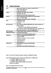
... 1 parallel port supporting Normal/EPP/ECP mode 1 Serial port (COMA) 8 USB 2.0/1.1 ports (rear x 4, front x 4 via cable) 1 front audio connector 1 PS/2 keyboard port 1 PS/2 mouse port Onboard Broadcom 5789 chip (10/100/1000 Mbit) 1 RJ 45 port Supported on the Win 2000/... / DDRII3 / DDRII4 at the same time. (please refer to 400Mhz when a. b. c. GA-8I945PL-G Motherboard - 10 - Supported on the Win 2000/XP operating systems (Note 1) For further CPU support information, please go to GIGABYTE's website. (Note 2) Memory frequency will be reduced from 533MHz down to page15) (Note ...
... 1 parallel port supporting Normal/EPP/ECP mode 1 Serial port (COMA) 8 USB 2.0/1.1 ports (rear x 4, front x 4 via cable) 1 front audio connector 1 PS/2 keyboard port 1 PS/2 mouse port Onboard Broadcom 5789 chip (10/100/1000 Mbit) 1 RJ 45 port Supported on the Win 2000/... / DDRII3 / DDRII4 at the same time. (please refer to 400Mhz when a. b. c. GA-8I945PL-G Motherboard - 10 - Supported on the Win 2000/XP operating systems (Note 1) For further CPU support information, please go to GIGABYTE's website. (Note 2) Memory frequency will be reduced from 533MHz down to page15) (Note ...
Manual
Page 11
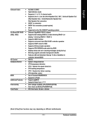
Center/Subwoofer Speaker Out ; Hardware Installation English Onboard Audio Š ALC882 CODEC Š High Definition Audio Š Supports 2 / 4 / 6 / 8 channel audio Š Supports Line In ; MIC ; Side Speaker Out connection Š SPDIF In connection Š SPDIF Out connection (coaxial+optical) Š CD In Š Supported on ...
Center/Subwoofer Speaker Out ; Hardware Installation English Onboard Audio Š ALC882 CODEC Š High Definition Audio Š Supports 2 / 4 / 6 / 8 channel audio Š Supports Line In ; MIC ; Side Speaker Out connection Š SPDIF In connection Š SPDIF Out connection (coaxial+optical) Š CD In Š Supported on ...

Manual
Page 17
...cable. COM A (Serial Port) Connects to the lower port (purple). COAXIAL (SPDIF Out) The SPDIF coaxial output port is capable of providing digital audio to external speakers or com pressed AC3 data to Surround Speaker Out (Rear Speaker Out) jack. - 17 - have a standard USB interface. Line ...Out (Front Speaker Out) The default Line Out (Front Speaker Out) jack. LAN Port The provided Internet connection is capable of providing digital audio to external speakers or • compressed AC3 data to MIC In jack. Devices like CD-ROM, walkman etc. English 1-6 I/O Back Panel ...
...cable. COM A (Serial Port) Connects to the lower port (purple). COAXIAL (SPDIF Out) The SPDIF coaxial output port is capable of providing digital audio to external speakers or com pressed AC3 data to Surround Speaker Out (Rear Speaker Out) jack. - 17 - have a standard USB interface. Line ...Out (Front Speaker Out) The default Line Out (Front Speaker Out) jack. LAN Port The provided Internet connection is capable of providing digital audio to external speakers or • compressed AC3 data to MIC In jack. Devices like CD-ROM, walkman etc. English 1-6 I/O Back Panel ...
Manual
Page 18
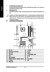
...Side Speaker Out The default Side Speaker Out jack. In addition to the default speakers settings, the ~ audio jacks can be reconfigured to perform different functions via the audio software. channel audio setup steps for detailed software configuration information. 1-7 Connectors Introduction 1 3 2 5 6 8 7 11 ...14) RF_ID 6) IDE1/IDE2/IDE3 15) CI 7) SATAII0 / SATAII1 / SATAII2 / SATAII3 16) CLR_CMOS 8) F_AUDIO 17) BAT 9) PWR_LED GA-8I945PL-G Motherboard - 18 - Only microphones still MUST be connected to Side Speaker Out jack. Please refer to the de- fault Mic In jack (...
...Side Speaker Out The default Side Speaker Out jack. In addition to the default speakers settings, the ~ audio jacks can be reconfigured to perform different functions via the audio software. channel audio setup steps for detailed software configuration information. 1-7 Connectors Introduction 1 3 2 5 6 8 7 11 ...14) RF_ID 6) IDE1/IDE2/IDE3 15) CI 7) SATAII0 / SATAII1 / SATAII2 / SATAII3 16) CLR_CMOS 8) F_AUDIO 17) BAT 9) PWR_LED GA-8I945PL-G Motherboard - 18 - Only microphones still MUST be connected to Side Speaker Out jack. Please refer to the de- fault Mic In jack (...

Manual
Page 22
..., please refer to the instructions on Page 69 about the software settings. 9) PWR_LED PWR_LED is on/off. For optional front panel audio module, please contact your chassis manufacturer. 1 2 HD Audio: Pin No. 1 2 3 4 5 6 7 8 9 10 9 10 Definition MIC2_L GND MIC2_R -ACZ_DET Line2_R FSENSE1 FAUDIO_JD...panel audio module. If you connect the front panel audio module. To connect an AC97 front panel audio module to this connector. It will make the audio device unable to indicate whether the system is connect with the system power indicator to work or even damage it. GA-8I945PL-G...
..., please refer to the instructions on Page 69 about the software settings. 9) PWR_LED PWR_LED is on/off. For optional front panel audio module, please contact your chassis manufacturer. 1 2 HD Audio: Pin No. 1 2 3 4 5 6 7 8 9 10 9 10 Definition MIC2_L GND MIC2_R -ACZ_DET Line2_R FSENSE1 FAUDIO_JD...panel audio module. If you connect the front panel audio module. To connect an AC97 front panel audio module to this connector. It will make the audio device unable to indicate whether the system is connect with the system power indicator to work or even damage it. GA-8I945PL-G...

Manual
Page 23
... Hardware System Open: Normal Close: Power On/Off Pin 1: LED anode(+) Pin 2: LED cathode(-) NC 11) CD_IN (CD IN) Connect CD-ROM or DVD-ROM audio out to the pin assignment below.
... Hardware System Open: Normal Close: Power On/Off Pin 1: LED anode(+) Pin 2: LED cathode(-) NC 11) CD_IN (CD IN) Connect CD-ROM or DVD-ROM audio out to the pin assignment below.

Manual
Page 38
... Enable onboard Serial port 1 and address is 2E8/IRQ3. Disabled Disable USB Keyboard Support. (Default value) USB Mouse Support Enabled Disabled Enable USB Mouse Support. GA-8I945PL-G Motherboard - 38 - Onboard H/W LAN Enabled Enable Onboard H/W LAN function. (Default value) Disabled Disable this function if you are not using onboard USB 2.0 feature. USB ...as RAID. (Default value) ATA Select onboard GigaRAID chip function asa ATA. Disable USB Mouse Support. (Default value) Azalia Codec Auto Auto detect Azalia audio function. (Default value) Disabled Disable Azalia...
... Enable onboard Serial port 1 and address is 2E8/IRQ3. Disabled Disable USB Keyboard Support. (Default value) USB Mouse Support Enabled Disabled Enable USB Mouse Support. GA-8I945PL-G Motherboard - 38 - Onboard H/W LAN Enabled Enable Onboard H/W LAN function. (Default value) Disabled Disable this function if you are not using onboard USB 2.0 feature. USB ...as RAID. (Default value) ATA Select onboard GigaRAID chip function asa ATA. Disable USB Mouse Support. (Default value) Azalia Codec Auto Auto detect Azalia audio function. (Default value) Disabled Disable Azalia...

Manual
Page 68
...) simultaneously. all at up to 192 kHz/24-bit quality and multi-streaming applications, HD Audio is able to the right. For example, if a rear speaker is applied. STEP 2: In the Audio Control Panel, click the Audio I/O tab. GA-8I945PL-G Motherboard - 68 - You are able to work correctly. Line In Line Out (Front Speaker Out...
...) simultaneously. all at up to 192 kHz/24-bit quality and multi-streaming applications, HD Audio is able to the right. For example, if a rear speaker is applied. STEP 2: In the Audio Control Panel, click the Audio I/O tab. GA-8I945PL-G Motherboard - 68 - You are able to work correctly. Line In Line Out (Front Speaker Out...

Manual
Page 69
...After plugging in Control Panel). The 2-channel audio setup is completed. 4 Channel Audio Setup STEP 1 : After installation of the audio driver, you should find an Audio Manager icon in your system tray (you can also find the icon in 4-channel speakers to open the Audio Control Panel. Choose a device depending on... of Front Speaker Out (Line Out) and Rear Speaker Out and then click OK. STEP 2: In the Audio Control Panel, click the Audio I/O tab. The 4-channel audio setup is completed. - 69 - STEP 3: After a speaker or headphone is plugged into the rear Line Out jack, a small window ...
...After plugging in Control Panel). The 2-channel audio setup is completed. 4 Channel Audio Setup STEP 1 : After installation of the audio driver, you should find an Audio Manager icon in your system tray (you can also find the icon in 4-channel speakers to open the Audio Control Panel. Choose a device depending on... of Front Speaker Out (Line Out) and Rear Speaker Out and then click OK. STEP 2: In the Audio Control Panel, click the Audio I/O tab. The 4-channel audio setup is completed. - 69 - STEP 3: After a speaker or headphone is plugged into the rear Line Out jack, a small window ...

Manual
Page 70
.../Subwoofer Speaker Out) then click OK. In the upper left list, click 6CH Speaker. GA-8I945PL-G Motherboard - 70 - STEP 3: After plugging in Control Panel). English 6 Channel Audio Setup STEP 1 : After installation of the audio driver, you should find an Audio Manager icon in your system tray (you can also find the icon in 6-channel speakers...
.../Subwoofer Speaker Out) then click OK. In the upper left list, click 6CH Speaker. GA-8I945PL-G Motherboard - 70 - STEP 3: After plugging in Control Panel). English 6 Channel Audio Setup STEP 1 : After installation of the audio driver, you should find an Audio Manager icon in your system tray (you can also find the icon in 6-channel speakers...
Manual
Page 71
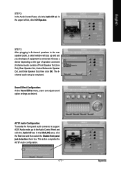
... is connected. STEP 2: In the Audio Control Panel, click the Audio I /O tab. STEP 3: After plugging in 8-channel speakers to the Audio Control Panel and click the Audio I /O tab. This action completes the AC'97 Audio configuration. - 71 - Sound Effect Configuration: At the Sound Effect menu, users ... 8CH Speaker. Choose a device depending on the type of speaker connected (8-channel audio consists of equipment is completed. AC'97 Audio Configuration: To enable the front panel audio connector to support AC97 Audio mode, go to the rear speaker jacks, a small window will pop up ...
... is connected. STEP 2: In the Audio Control Panel, click the Audio I /O tab. STEP 3: After plugging in 8-channel speakers to the Audio Control Panel and click the Audio I /O tab. This action completes the AC'97 Audio configuration. - 71 - Sound Effect Configuration: At the Sound Effect menu, users ... 8CH Speaker. Choose a device depending on the type of speaker connected (8-channel audio consists of equipment is completed. AC'97 Audio Configuration: To enable the front panel audio connector to support AC97 Audio mode, go to the rear speaker jacks, a small window will pop up ...


