Manual
Page 1
GA-890GPA-UD3H AM3+ socket motherboard for AMD Phenom™ II processor/AMD Athlon™ II processor User's Manual Rev. 3101 12ME-890GPA3-3101R
GA-890GPA-UD3H AM3+ socket motherboard for AMD Phenom™ II processor/AMD Athlon™ II processor User's Manual Rev. 3101 12ME-890GPA3-3101R

Manual
Page 2
Motherboard GA-890GPA-UD3H Jan. 11, 2011 Motherboard GA-890GPA-UD3H Jan. 11, 2011
Motherboard GA-890GPA-UD3H Jan. 11, 2011 Motherboard GA-890GPA-UD3H Jan. 11, 2011

Manual
Page 3
... trademarks mentioned in this : "REV: X.X." Check your motherboard looks like this manual may be made by GIGABYTE without GIGABYTE's prior written permission. For product-related information, check on our website at: http://www.gigabyte.com Identifying Your Motherboard Revision The revision number on your motherboard revision before updating motherboard BIOS, drivers, or when looking for technical information...
... trademarks mentioned in this : "REV: X.X." Check your motherboard looks like this manual may be made by GIGABYTE without GIGABYTE's prior written permission. For product-related information, check on our website at: http://www.gigabyte.com Identifying Your Motherboard Revision The revision number on your motherboard revision before updating motherboard BIOS, drivers, or when looking for technical information...

Manual
Page 4
Table of Contents Box Contents...6 Optional Items...6 GA-890GPA-UD3H Motherboard Layout 7 GA-890GPA-UD3H Motherboard Block Diagram 8 Chapter 1 Hardware Installation 9 1-1 Installation Precautions 9 1-2 Product Specifications 10 1-3 Installing the CPU and CPU Cooler 13 1-3-1 Installing the CPU 13 1-3-2 Installing the CPU Cooler ...
Table of Contents Box Contents...6 Optional Items...6 GA-890GPA-UD3H Motherboard Layout 7 GA-890GPA-UD3H Motherboard Block Diagram 8 Chapter 1 Hardware Installation 9 1-1 Installation Precautions 9 1-2 Product Specifications 10 1-3 Installing the CPU and CPU Cooler 13 1-3-1 Installing the CPU 13 1-3-2 Installing the CPU Cooler ...

Manual
Page 6
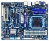
... No. 12CF1-2SERPW-0*R) S/PDIF In cable (Part No. 12CR1-1SPDIN-0*R) COM port cable (Part No. 12CF1-1CM001-3*R) - 6 - Box Contents GA-890GPA-UD3H motherboard Motherboard driver disk User's Manual Quick Installation Guide One IDE cable Four SATA cables I/O Shield • The box contents above are subject to change without notice.... • The motherboard image is for reference only and the actual items shall depend on the product package you obtain. The box contents are for reference ...
... No. 12CF1-2SERPW-0*R) S/PDIF In cable (Part No. 12CR1-1SPDIN-0*R) COM port cable (Part No. 12CF1-1CM001-3*R) - 6 - Box Contents GA-890GPA-UD3H motherboard Motherboard driver disk User's Manual Quick Installation Guide One IDE cable Four SATA cables I/O Shield • The box contents above are subject to change without notice.... • The motherboard image is for reference only and the actual items shall depend on the product package you obtain. The box contents are for reference ...

Manual
Page 7
... COM F_USB4 F_USB2 SYS_FAN1 FDD F_1394_2 F_USB3 F_USB1 - 7 - GA-890GPA-UD3H Motherboard Layout KB__MS_USB ATX_12V CPU_FAN VGA_DVI ATX Socket AM3+/AM3 HDMI_SPDIF USB_1394 PWR_FAN USB30_LAN Renesas D720200 F_AUDIO AUDIO AMD SidePort PCIEX1_1 890GX Memory IDE DDR3_1 DDR3_2 DDR3_3 DDR3_4 SYS_FAN2 Realtek RTL8111D/E PCIEX16 GIGABYTE SATA2 CD_IN PCIEX1_2 GA-890GPA-UD3H CODEC CLR_CMOS PCIEX1_3 BAT SPDIF_OUT SPDIF_IN PCIEX8 AMD...
... COM F_USB4 F_USB2 SYS_FAN1 FDD F_1394_2 F_USB3 F_USB1 - 7 - GA-890GPA-UD3H Motherboard Layout KB__MS_USB ATX_12V CPU_FAN VGA_DVI ATX Socket AM3+/AM3 HDMI_SPDIF USB_1394 PWR_FAN USB30_LAN Renesas D720200 F_AUDIO AUDIO AMD SidePort PCIEX1_1 890GX Memory IDE DDR3_1 DDR3_2 DDR3_3 DDR3_4 SYS_FAN2 Realtek RTL8111D/E PCIEX16 GIGABYTE SATA2 CD_IN PCIEX1_2 GA-890GPA-UD3H CODEC CLR_CMOS PCIEX1_3 BAT SPDIF_OUT SPDIF_IN PCIEX8 AMD...

Manual
Page 8
... HDMI is populated, the PCIEX16 slot will operate at up to install it in the PCIEX16 slot. When the PCIEX8 slot is not supported. - 8 - GA-890GPA-UD3H Motherboard Block Diagram 1 PCI Express x16 (Note 1)2 PCI Express x8 (Note 1) CPU CLK+/- (200 MHz) PCIe CLK (100 MHz) AM3+/AM3 CPU DDR3 1866...AMD 890GX Renesas PCIe CLK D720200 (100 MHz) 3 PCI Express x1 2 USB 3.0/2.0 6 SATA 6Gb/s ATA-133/100/66/33 IDE Channel 2 SATA 3Gb/s GIGABYTE SATA2 AMD SB850 GFX CLK (100 MHz) D-Sub DVI-D (Note 2) HDMI (Note 2) DDR3 SidePort Memory 12 USB 2.0/1.1 Dual BIOS PCI Express Bus PCI Bus T.I....
... HDMI is populated, the PCIEX16 slot will operate at up to install it in the PCIEX16 slot. When the PCIEX8 slot is not supported. - 8 - GA-890GPA-UD3H Motherboard Block Diagram 1 PCI Express x16 (Note 1)2 PCI Express x8 (Note 1) CPU CLK+/- (200 MHz) PCIe CLK (100 MHz) AM3+/AM3 CPU DDR3 1866...AMD 890GX Renesas PCIe CLK D720200 (100 MHz) 3 PCI Express x1 2 USB 3.0/2.0 6 SATA 6Gb/s ATA-133/100/66/33 IDE Channel 2 SATA 3Gb/s GIGABYTE SATA2 AMD SB850 GFX CLK (100 MHz) D-Sub DVI-D (Note 2) HDMI (Note 2) DDR3 SidePort Memory 12 USB 2.0/1.1 Dual BIOS PCI Express Bus PCI Bus T.I....

Manual
Page 9
... Always remove the AC power by your hands dry and first touch a metal object to eliminate static electricity. • Prior to installing the motherboard, please have a problem related to the use of the product, please consult a certified computer technician. - 9 - Hardware Installation ponents such as... a result of your hardware components are connected tightly and securely. • When handling the motherboard, avoid touching any installation steps or have it on top of an antistatic pad or within the computer casing. • Do not place ...
... Always remove the AC power by your hands dry and first touch a metal object to eliminate static electricity. • Prior to installing the motherboard, please have a problem related to the use of the product, please consult a certified computer technician. - 9 - Hardware Installation ponents such as... a result of your hardware components are connected tightly and securely. • When handling the motherboard, avoid touching any installation steps or have it on top of an antistatic pad or within the computer casing. • Do not place ...

Manual
Page 12
... Center ŠŠ Support for Xpress Install ŠŠ Support for Xpress Recovery2 ŠŠ Support for EasyTune * Available functions in EasyTune may differ by motherboard model. ŠŠ Support for Easy Energy Saver ŠŠ Support for Smart Recovery ŠŠ Support for Auto Green ŠŠ Support for ON...
... Center ŠŠ Support for Xpress Install ŠŠ Support for Xpress Recovery2 ŠŠ Support for EasyTune * Available functions in EasyTune may differ by motherboard model. ŠŠ Support for Easy Energy Saver ŠŠ Support for Smart Recovery ŠŠ Support for Auto Green ŠŠ Support for ON...

Manual
Page 13
... standard requirements for the latest CPU support list.) • Always turn on the computer if the CPU cooler is not recommended that the motherboard supports the CPU. (Go to GIGABYTE's website for the peripherals. If you may occur. • Set the CPU host frequency in accordance with the CPU specifications. Locate the...
... standard requirements for the latest CPU support list.) • Always turn on the computer if the CPU cooler is not recommended that the motherboard supports the CPU. (Go to GIGABYTE's website for the peripherals. If you may occur. • Set the CPU host frequency in accordance with the CPU specifications. Locate the...

Manual
Page 14
... Locking Lever Step 1: Completely lift up the CPU socket locking lever. Hardware Installation - 14 - Follow the steps below to correctly install the CPU into the motherboard CPU socket. • Before installing the CPU, make sure to turn off the computer and unplug the power cord from the power outlet to prevent...
... Locking Lever Step 1: Completely lift up the CPU socket locking lever. Hardware Installation - 14 - Follow the steps below to correctly install the CPU into the motherboard CPU socket. • Before installing the CPU, make sure to turn off the computer and unplug the power cord from the power outlet to prevent...

Manual
Page 15
... the retention frame. 1-3-2 Installing the CPU Cooler Follow the steps below to correctly install the CPU cooler on the CPU. (The following procedure uses the GIGABYTE cooler as the picture above shows) to lock into place. (Refer to your CPU cooler installation manual for instructions on the...
... the retention frame. 1-3-2 Installing the CPU Cooler Follow the steps below to correctly install the CPU cooler on the CPU. (The following procedure uses the GIGABYTE cooler as the picture above shows) to lock into place. (Refer to your CPU cooler installation manual for instructions on the...

Manual
Page 16
After the memory is installed. 2. Dual Channel mode cannot be used . (Go to GIGABYTE's website for optimum performance. 1-4 Installing the Memory Read the following guidelines before you are divided into two channels and each channel ..., DS=Double-Sided, "- -"=No Memory) DDR3_1 DDR3_2 DDR3_3 DDR3_4 Due to insert the memory, switch the direction. 1-4-1 Dual Channel Memory Configuration This motherboard provides four DDR3 memory sockets and supports Dual Channel Technology. The four DDR3 memory sockets are unable to CPU limitations, read the following : Channel 0: ...
After the memory is installed. 2. Dual Channel mode cannot be used . (Go to GIGABYTE's website for optimum performance. 1-4 Installing the Memory Read the following guidelines before you are divided into two channels and each channel ..., DS=Double-Sided, "- -"=No Memory) DDR3_1 DDR3_2 DDR3_3 DDR3_4 Due to insert the memory, switch the direction. 1-4-1 Dual Channel Memory Configuration This motherboard provides four DDR3 memory sockets and supports Dual Channel Technology. The four DDR3 memory sockets are unable to CPU limitations, read the following : Channel 0: ...

Manual
Page 17
... off the computer and unplug the power cord from the power outlet to prevent damage to the memory module. Place the memory module on this motherboard.
... off the computer and unplug the power cord from the power outlet to prevent damage to the memory module. Place the memory module on this motherboard.
Manual
Page 18
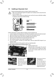
... your expansion card(s). 7. 1-5 Installing an Expansion Card Read the following guidelines before installing an expansion card to install an expansion card: • Make sure the motherboard supports the expansion card. Make sure the metal contacts on the top edge of the PCI Express slot to the chassis back panel with the...
... your expansion card(s). 7. 1-5 Installing an Expansion Card Read the following guidelines before installing an expansion card to install an expansion card: • Make sure the motherboard supports the expansion card. Make sure the metal contacts on the top edge of the PCI Express slot to the chassis back panel with the...

Manual
Page 19
... CrossFireX bridge connectors (Note) - Windows 7, Vista, or Windows XP operating system - Procedure and driver screen for more information about enabling CrossFireX technology. - 19 - A CrossFireX-supported motherboard with sufficient power is recommended (Refer to the CrossFireX menu and ensure the Enable CrossFireX™ check box is selected. (Note) The bridge connectors may...
... CrossFireX bridge connectors (Note) - Windows 7, Vista, or Windows XP operating system - Procedure and driver screen for more information about enabling CrossFireX technology. - 19 - A CrossFireX-supported motherboard with sufficient power is recommended (Refer to the CrossFireX menu and ensure the Enable CrossFireX™ check box is selected. (Note) The bridge connectors may...

Manual
Page 20
... Set Surround View to UMA+SidePort. (Note 2) - Windows 7/Vista operating system - C. Configuring the Graphics Driver After installing the motherboard driver in "1-5 Installing an Expansion Card" and install an ATI Hybrid CrossFireX-supported graphics card on configuring an ATI Hybrid CrossFireX system.... Read the following items under the Advanced BIOS Features menu: - An ATI Hybrid CrossFireX-supported motherboard and correct driver - Connecting the Graphics Cards Step 1: Observe the steps in the operating system, go to disable the...
... Set Surround View to UMA+SidePort. (Note 2) - Windows 7/Vista operating system - C. Configuring the Graphics Driver After installing the motherboard driver in "1-5 Installing an Expansion Card" and install an ATI Hybrid CrossFireX-supported graphics card on configuring an ATI Hybrid CrossFireX system.... Read the following items under the Advanced BIOS Features menu: - An ATI Hybrid CrossFireX-supported motherboard and correct driver - Connecting the Graphics Cards Step 1: Observe the steps in the operating system, go to disable the...

Manual
Page 22
Do not rock it straight out from the motherboard. • When removing the cable, pull it side to side to the recommended system requirements (or better) below shows the supported dual display ...port does not support D-Sub connection by adapter. (Note 2) Simultaneous output for DVI-D and HDMI is compatible to 1 Gbps data rate. Dual Display Configurations: This motherboard provides three ports for more information) • Playback software: CyberLink PowerDVD 8.0 or later (Note: Please ensure Hardware Acceleration is enabled.) • HDCP compliant monitor(s)...
Do not rock it straight out from the motherboard. • When removing the cable, pull it side to side to the recommended system requirements (or better) below shows the supported dual display ...port does not support D-Sub connection by adapter. (Note 2) Simultaneous output for DVI-D and HDMI is compatible to 1 Gbps data rate. Dual Display Configurations: This motherboard provides three ports for more information) • Playback software: CyberLink PowerDVD 8.0 or later (Note: Please ensure Hardware Acceleration is enabled.) • HDCP compliant monitor(s)...

Manual
Page 24
...) CD_IN 14) SPDIF_IN 15) SPDIF_OUT 16) F_USB1/F_USB2/F_USB3/F_USB4 17) F_1394_1/F_1394_2 18) COM 19) CLR_CMOS Read the following guidelines before turning on the motherboard. Hardware Installation - 24 - Unplug the power cord from the power outlet to prevent damage to the devices. • After installing the device and before connecting...
...) CD_IN 14) SPDIF_IN 15) SPDIF_OUT 16) F_USB1/F_USB2/F_USB3/F_USB4 17) F_1394_1/F_1394_2 18) COM 19) CLR_CMOS Read the following guidelines before turning on the motherboard. Hardware Installation - 24 - Unplug the power cord from the power outlet to prevent damage to the devices. • After installing the device and before connecting...

Manual
Page 25
... mainly supplies power to the power connector in the correct orientation. To meet expansion requirements, it is turned off and all the components on the motherboard. 1/2) ATX_12V/ATX (2x4 12V Power Connector and 2x12 Main Power Connector) With the use of the power connector, the power supply can withstand high power...
... mainly supplies power to the power connector in the correct orientation. To meet expansion requirements, it is turned off and all the components on the motherboard. 1/2) ATX_12V/ATX (2x4 12V Power Connector and 2x12 Main Power Connector) With the use of the power connector, the power supply can withstand high power...


