Manual
Page 1
GA-890GPA-UD3H AM3+ socket motherboard for AMD Phenom™ II processor/AMD Athlon™ II processor User's Manual Rev. 3101 12ME-890GPA3-3101R
GA-890GPA-UD3H AM3+ socket motherboard for AMD Phenom™ II processor/AMD Athlon™ II processor User's Manual Rev. 3101 12ME-890GPA3-3101R

Manual
Page 3
... with the product. For detailed product information, carefully read the User's Manual. For product-related information, check on our website at: http://www.gigabyte.com Identifying Your Motherboard Revision The revision number on your motherboard revision before updating motherboard... means the revision of the motherboard is the property of this manual may be reproduced, copied, translated, transmitted, or published in this manual may be made by any form or by GIGABYTE without GIGABYTE's prior written permission. Disclaimer Information in any means without prior ...
... with the product. For detailed product information, carefully read the User's Manual. For product-related information, check on our website at: http://www.gigabyte.com Identifying Your Motherboard Revision The revision number on your motherboard revision before updating motherboard... means the revision of the motherboard is the property of this manual may be reproduced, copied, translated, transmitted, or published in this manual may be made by any form or by GIGABYTE without GIGABYTE's prior written permission. Disclaimer Information in any means without prior ...

Manual
Page 5
Chapter 3 Drivers Installation 61 3-1 Installing Chipset Drivers 61 3-2 Application Software 62 3-3 Technical Manuals 62 3-4 Contact...63 3-5 System...63 3-6 Download Center 64 3-7 New Utilities...64 Chapter 4 Unique Features 65 4-1 Xpress Recovery2 65 4-2... Auto Green...77 4-8 Cloud OC...78 Chapter 5 Appendix...79 5-1 Configuring SATA Hard Drive(s 79 5-1-1 Configuring AMD SB850 SATA Controller 79 5-1-2 Configuring GIGABYTE SATA2 SATA Controller 85 5-1-3 Making a SATA RAID/AHCI Driver Diskette 91 5-1-4 Installing the SATA RAID/AHCI Driver and Operating System 93 5-2 Configuring Audio...
Chapter 3 Drivers Installation 61 3-1 Installing Chipset Drivers 61 3-2 Application Software 62 3-3 Technical Manuals 62 3-4 Contact...63 3-5 System...63 3-6 Download Center 64 3-7 New Utilities...64 Chapter 4 Unique Features 65 4-1 Xpress Recovery2 65 4-2... Auto Green...77 4-8 Cloud OC...78 Chapter 5 Appendix...79 5-1 Configuring SATA Hard Drive(s 79 5-1-1 Configuring AMD SB850 SATA Controller 79 5-1-2 Configuring GIGABYTE SATA2 SATA Controller 85 5-1-3 Making a SATA RAID/AHCI Driver Diskette 91 5-1-4 Installing the SATA RAID/AHCI Driver and Operating System 93 5-2 Configuring Audio...

Manual
Page 6
... power cable (Part No. 12CF1-2SERPW-0*R) S/PDIF In cable (Part No. 12CR1-1SPDIN-0*R) COM port cable (Part No. 12CF1-1CM001-3*R) - 6 - Box Contents GA-890GPA-UD3H motherboard Motherboard driver disk User's Manual Quick Installation Guide One IDE cable Four SATA cables I/O Shield • The box contents above are subject to change without notice. • The...
... power cable (Part No. 12CF1-2SERPW-0*R) S/PDIF In cable (Part No. 12CR1-1SPDIN-0*R) COM port cable (Part No. 12CF1-1CM001-3*R) - 6 - Box Contents GA-890GPA-UD3H motherboard Motherboard driver disk User's Manual Quick Installation Guide One IDE cable Four SATA cables I/O Shield • The box contents above are subject to change without notice. • The...

Manual
Page 9
.... • It is best to wear an electrostatic discharge (ESD) wrist strap when handling electronic com- Hardware Installation Prior to installation, carefully read the user's manual and follow these procedures: • Prior to the use of electrostatic discharge (ESD). These stickers are required for warranty validation. • Always remove the AC...
.... • It is best to wear an electrostatic discharge (ESD) wrist strap when handling electronic com- Hardware Installation Prior to installation, carefully read the user's manual and follow these procedures: • Prior to the use of electrostatic discharge (ESD). These stickers are required for warranty validation. • Always remove the AC...

Manual
Page 15
... the steps below to correctly install the CPU cooler on the CPU. (The following procedure uses the GIGABYTE cooler as the picture above shows) to lock into place. (Refer to your CPU cooler installation manual for instructions on installing the cooler.) Step 5: Finally, attach the power connector of the installed CPU. Use...
... the steps below to correctly install the CPU cooler on the CPU. (The following procedure uses the GIGABYTE cooler as the picture above shows) to lock into place. (Refer to your CPU cooler installation manual for instructions on installing the cooler.) Step 5: Finally, attach the power connector of the installed CPU. Use...
Manual
Page 18
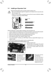
... and Removing a PCI Express Graphics Card: • Installing a Graphics Card: Gently push down on your card. Install the driver provided with a screw. 5. Carefully read the manual that supports your computer. Remove the metal slot cover from the slot. If necessary, go to BIOS Setup to make any required BIOS changes for...
... and Removing a PCI Express Graphics Card: • Installing a Graphics Card: Gently push down on your card. Install the driver provided with a screw. 5. Carefully read the manual that supports your computer. Remove the metal slot cover from the slot. If necessary, go to BIOS Setup to make any required BIOS changes for...

Manual
Page 19
...cards for the power requirement) B. Browse to the CrossFireX menu and ensure the Enable CrossFireX™ check box is recommended (Refer to the manual of the two cards. 1-6 Setup of identical brand and chip and correct driver - Configuring the Graphics Card Driver After installing the graphics ...card driver in the operating system, go to the manual that came with two PCI Express x16 slots and correct driver - Step 3: Plug the display cable into the graphics card on your ...
...cards for the power requirement) B. Browse to the CrossFireX menu and ensure the Enable CrossFireX™ check box is recommended (Refer to the manual of the two cards. 1-6 Setup of identical brand and chip and correct driver - Configuring the Graphics Card Driver After installing the graphics ...card driver in the operating system, go to the manual that came with two PCI Express x16 slots and correct driver - Step 3: Plug the display cable into the graphics card on your ...
Manual
Page 31
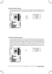
... graphics card and have digital audio output from your expansion card. Pin No. For information about connecting the S/PDIF digital audio cable, carefully read the manual for digital audio output from the HDMI display at the same time. Hardware Installation Definition 1 1 SPDIFO 2 GND - 31 - Definition 1 Power 2 SPDIFI 3 GND 15) SPDIF_OUT (S/PDIF...
... graphics card and have digital audio output from your expansion card. Pin No. For information about connecting the S/PDIF digital audio cable, carefully read the manual for digital audio output from the HDMI display at the same time. Hardware Installation Definition 1 1 SPDIFO 2 GND - 31 - Definition 1 Power 2 SPDIFI 3 GND 15) SPDIF_OUT (S/PDIF...

Manual
Page 33
... do so may cause damage to the motherboard. • After system restart, go to BIOS Setup to load factory defaults (select Load Optimized Defaults) or manually configure the BIOS settings (refer to remove the jumper cap from the jumper. 18) COM (Serial Port Header) The COM header can provide one serial...
... do so may cause damage to the motherboard. • After system restart, go to BIOS Setup to load factory defaults (select Load Optimized Defaults) or manually configure the BIOS settings (refer to remove the jumper cap from the jumper. 18) COM (Serial Port Header) The COM header can provide one serial...
Manual
Page 40
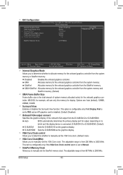
...of system memory allocated solely for display. BIOS Setup - 40 - This option is configurable only if Init Display First is set to manually set to 2000 MHz. MS-DOS, for example, will use only this memory for the onboard graphics controller. Auto BIOS automatically determines the...SidePort memory. (Default) UMA Frame Buffer Size Frame buffer size is the total amount of the onboard VGA output from 200 MHz to Manual. IGX Configuration CMOS Setup Utility-Copyright (C) 1984-2010 Award Software IGX Configuration Internal Graphics Mode UMA Frame Buffer Size x Surround View Onboard...
...of system memory allocated solely for display. BIOS Setup - 40 - This option is configurable only if Init Display First is set to manually set to 2000 MHz. MS-DOS, for example, will use only this memory for the onboard graphics controller. Auto BIOS automatically determines the...SidePort memory. (Default) UMA Frame Buffer Size Frame buffer size is the total amount of the onboard VGA output from 200 MHz to Manual. IGX Configuration CMOS Setup Utility-Copyright (C) 1984-2010 Award Software IGX Configuration Internal Graphics Mode UMA Frame Buffer Size x Surround View Onboard...

Manual
Page 41
...Sets Memory Clock to X6.66. BIOS Setup CPU NorthBridge Freq. CPU Frequency(MHz) Allows you to manually set to Manual. The adjustable range is set the PCIe clock frequency. Manual allows the memory clock control item below to be set the CPU host frequency. X6.66 Sets Memory ...Clock to X5.33. The adjustable range is highly recommended that the CPU frequency be configurable. PCIE Clock(MHz) Allows you to manually set in accordance with the CPU specifications. Auto BIOS will automatically adjust the HT Link Width. (Default) 8 bit Sets HT Link Width to...
...Sets Memory Clock to X6.66. BIOS Setup CPU NorthBridge Freq. CPU Frequency(MHz) Allows you to manually set to Manual. The adjustable range is set the PCIe clock frequency. Manual allows the memory clock control item below to be set the CPU host frequency. X6.66 Sets Memory ...Clock to X5.33. The adjustable range is highly recommended that the CPU frequency be configurable. PCIE Clock(MHz) Allows you to manually set in accordance with the CPU specifications. Auto BIOS will automatically adjust the HT Link Width. (Default) 8 bit Sets HT Link Width to...

Manual
Page 42
... are : Auto (default), 4T~12T. RAS to be configurable. Unganged Sets memory control mode to two single-channel. (Default) DDR3 Timing Items Manual allows all DDR3 Timing items below to CAS R/W Delay Options are: Auto (default), 5T~12T. Auto 5T 5T Auto 110ns 110ns Auto -- --... CAS# latency Options are : Auto (default), Manual. DRAM Configuration CMOS Setup Utility-Copyright (C) 1984-2010 Award Software DRAM Configuration DCTs Mode DDR3 Timing Items x CAS# latency x RAS to CAS R/W...
... are : Auto (default), 4T~12T. RAS to be configurable. Unganged Sets memory control mode to two single-channel. (Default) DDR3 Timing Items Manual allows all DDR3 Timing items below to CAS R/W Delay Options are: Auto (default), 5T~12T. Auto 5T 5T Auto 110ns 110ns Auto -- --... CAS# latency Options are : Auto (default), Manual. DRAM Configuration CMOS Setup Utility-Copyright (C) 1984-2010 Award Software DRAM Configuration DCTs Mode DDR3 Timing Items x CAS# latency x RAS to CAS R/W...

Manual
Page 44
...automatically set memory voltage. Normal Supplies the North Bridge voltage as required. Note: Increasing CPU voltage may result in damage to 1.600V. Manual allows all voltage control items below to be configurable. (Default: Auto) CPU PLL Voltage Control Allows you to set the system voltages as...220V to set the memory VTT voltage. NB Voltage Control Allows you to 3.100V. NB/PCIe/PLL Voltage Control Allows you to manually set the North Bridge voltage. Note: Increasing memory voltage may result in damage to the memory or reduce the useful life of ...
...automatically set memory voltage. Normal Supplies the North Bridge voltage as required. Note: Increasing CPU voltage may result in damage to 1.600V. Manual allows all voltage control items below to be configurable. (Default: Auto) CPU PLL Voltage Control Allows you to set the system voltages as...220V to set the memory VTT voltage. NB Voltage Control Allows you to 3.100V. NB/PCIe/PLL Voltage Control Allows you to manually set the North Bridge voltage. Note: Increasing memory voltage may result in damage to the memory or reduce the useful life of ...

Manual
Page 47
... for a keyboard or a floppy disk drive error but stop for all other errors. Precomp Write precompensation cylinder. Drive A Allows you wish to enter the parameters manually, refer to the information on this channel. • Auto Lets the BIOS automatically detect IDE/SATA devices during the POST. (Default) • None If no...
... for a keyboard or a floppy disk drive error but stop for all other errors. Precomp Write precompensation cylinder. Drive A Allows you wish to enter the parameters manually, refer to the information on this channel. • Auto Lets the BIOS automatically detect IDE/SATA devices during the POST. (Default) • None If no...

Manual
Page 48
... to run multiple operating systems and applications in this submenu are synchronous to those under the same items on the CPU being used). (Default) Manual Allows you to manually enable/disable CPU Core 1/2/3/4/5. CPU Unlock (Note) Allows you to determine whether to unlock hidden CPU cores. (Default: Disabled) CPU core Control Allows...
... to run multiple operating systems and applications in this submenu are synchronous to those under the same items on the CPU being used). (Default) Manual Allows you to manually enable/disable CPU Core 1/2/3/4/5. CPU Unlock (Note) Allows you to determine whether to unlock hidden CPU cores. (Default: Disabled) CPU core Control Allows...

Manual
Page 61
Or click Install Single Items to manually select the drivers you want to manually select the utilities to install on the Application Software page later. • For USB 2.0 driver support under the Windows XP operating system, please install the ... still exists in Universal Serial Bus Controller in the screen shot below. (If the driver Autorun screen does not appear automatically, go to install new GIGABYTE utilities. The driver Autorun screen is installing the drivers. Or click No if you wish to automatically install the utilities. Chapter 3 Drivers Installation • Before...
Or click Install Single Items to manually select the drivers you want to manually select the utilities to install on the Application Software page later. • For USB 2.0 driver support under the Windows XP operating system, please install the ... still exists in Universal Serial Bus Controller in the screen shot below. (If the driver Autorun screen does not appear automatically, go to install new GIGABYTE utilities. The driver Autorun screen is installing the drivers. Or click No if you wish to automatically install the utilities. Chapter 3 Drivers Installation • Before...

Manual
Page 62
You can click the Install button on the right of an item to install it. 3-3 Technical Manuals This page provides GIGABYTE's application guides, content descriptions for this driver disk, and the motherboard manuals. 3-2 Application Software This page displays all the utilities and applications that GIGABYTE develops and some free software. Drivers Installation - 62 -
You can click the Install button on the right of an item to install it. 3-3 Technical Manuals This page provides GIGABYTE's application guides, content descriptions for this driver disk, and the motherboard manuals. 3-2 Application Software This page displays all the utilities and applications that GIGABYTE develops and some free software. Drivers Installation - 62 -

Manual
Page 68
...SATA controller, use FAT32/16/12 file system. 3. However, if the BIOS update file is potentially risky, please do it with the Q-Flash Utility A. GA-890GPA-UD3H FBe . . . . : BIOS Setup : XpressRecovery2 : Boot Menu : Qflash 05/24/2010-RS880D-SB850-7A66BG0CC-00 Because BIOS flashing is saved to... features the DualBIOS™ design, which enhances protection for the safety and stability of system safety, users cannot update the backup BIOS manually. GIGABYTE Q-Flash and @BIOS are easy-to-use and allow you to enter operating systems like MS-DOS or Window first. Normally, the...
...SATA controller, use FAT32/16/12 file system. 3. However, if the BIOS update file is potentially risky, please do it with the Q-Flash Utility A. GA-890GPA-UD3H FBe . . . . : BIOS Setup : XpressRecovery2 : Boot Menu : Qflash 05/24/2010-RS880D-SB850-7A66BG0CC-00 Because BIOS flashing is saved to... features the DualBIOS™ design, which enhances protection for the safety and stability of system safety, users cannot update the backup BIOS manually. GIGABYTE Q-Flash and @BIOS are easy-to-use and allow you to enter operating systems like MS-DOS or Window first. Normally, the...

Manual
Page 71
... file could cause your system not to start. 3. Using @BIOS 1. Update the BIOS Using the Internet Update Function: Click Update BIOS from GIGABYTE Server, select the @BIOS server site closest to complete. 3. Follow the on-screen instructions to your location and then download the BIOS file .... B. Make sure that is not present on -screen instructions to complete. Follow the on the @BIOS server site, please manually download the BIOS update file from GIGABYTE's website and follow the instructions in a corrupted BIOS or a system that the BIOS file to save the BIOS update file ...
... file could cause your system not to start. 3. Using @BIOS 1. Update the BIOS Using the Internet Update Function: Click Update BIOS from GIGABYTE Server, select the @BIOS server site closest to complete. 3. Follow the on-screen instructions to your location and then download the BIOS file .... B. Make sure that is not present on -screen instructions to complete. Follow the on the @BIOS server site, please manually download the BIOS update file from GIGABYTE's website and follow the instructions in a corrupted BIOS or a system that the BIOS file to save the BIOS update file ...


