
Manual
Page 4
Table of Contents Box Contents...6 Optional Items...6 GA-880G-UD3H Motherboard Layout 7 GA-880G-UD3H Motherboard Block Diagram 8 Chapter 1 Hardware Installation 9 1-1 Installation Precautions 9 1-2 Product Specifications 10 1-3 Installing the CPU and CPU Cooler 13 1-3-1 Installing the CPU 13 1-3-2 Installing the CPU Cooler 15 1-4 Installing the Memory 16 1-4-1 Dual Channel Memory Configuration 16 1-4-2 Installing a Memory 17 1-5 Installing an Expansion Card 18 1-6 Setup...
Table of Contents Box Contents...6 Optional Items...6 GA-880G-UD3H Motherboard Layout 7 GA-880G-UD3H Motherboard Block Diagram 8 Chapter 1 Hardware Installation 9 1-1 Installation Precautions 9 1-2 Product Specifications 10 1-3 Installing the CPU and CPU Cooler 13 1-3-1 Installing the CPU 13 1-3-2 Installing the CPU Cooler 15 1-4 Installing the Memory 16 1-4-1 Dual Channel Memory Configuration 16 1-4-2 Installing a Memory 17 1-5 Installing an Expansion Card 18 1-6 Setup...

Manual
Page 8
...PCI CLK (33 MHz) (Note 1) (Note 2) (Note 3) To reach DDR3 1866 MHz or above, you must install two memory modules and install them in the DDR3_3 and DDR3_4 memory sockets. GA-880G-UD3H Motherboard Block Diagram 1 PCI Express x16 1 PCI Express x4 (Note 3) AM3 CPU CPU CLK+/- (200 MHz) DDR3 1866 (O.C.) ...(Note 1)/ 1333/1066 MHz Dual Channel Memory PCIe CLK (100 MHz) Hyper Transport 3.0 GFX CLK (100 MHz) ...
...PCI CLK (33 MHz) (Note 1) (Note 2) (Note 3) To reach DDR3 1866 MHz or above, you must install two memory modules and install them in the DDR3_3 and DDR3_4 memory sockets. GA-880G-UD3H Motherboard Block Diagram 1 PCI Express x16 1 PCI Express x4 (Note 3) AM3 CPU CPU CLK+/- (200 MHz) DDR3 1866 (O.C.) ...(Note 1)/ 1333/1066 MHz Dual Channel Memory PCIe CLK (100 MHz) Hyper Transport 3.0 GFX CLK (100 MHz) ...

Manual
Page 9
... place the computer system in a high-temperature environment. • Turning on the computer power during the installation process can become damaged as a motherboard, CPU or memory. Prior to installation, carefully read the user's manual and follow these procedures: • Prior to installation, do not allow screws to come in contact with...
... place the computer system in a high-temperature environment. • Turning on the computer power during the installation process can become damaged as a motherboard, CPU or memory. Prior to installation, carefully read the user's manual and follow these procedures: • Prior to installation, do not allow screws to come in contact with...
Manual
Page 10
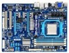
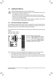
...; w North Bridge: AMD 880G South Bridge: AMD SB710 4 x 1.5V DDR3 DIMM sockets supporting up to 16 GB of system memory (Note 1) Dual channel memory architecture Support for DDR3 1866 (O.C.) (Note 2)/1333/1066 MHz memory modules (Go to GIGABYTE's website for the latest supported memory speeds and memory modules.) North Bridge: - 1 x D-Sub port - 1 x DVI...
...; w North Bridge: AMD 880G South Bridge: AMD SB710 4 x 1.5V DDR3 DIMM sockets supporting up to 16 GB of system memory (Note 1) Dual channel memory architecture Support for DDR3 1866 (O.C.) (Note 2)/1333/1066 MHz memory modules (Go to GIGABYTE's website for the latest supported memory speeds and memory modules.) North Bridge: - 1 x D-Sub port - 1 x DVI...

Manual
Page 12
.../XP Form Factor w ATX Form Factor; 30.5cm x 22.9cm (Note 1) Due to Windows 32-bit operating system limitation, when more than 4 GB of physical memory is installed, the actual memory size displayed will be less than 4 GB. (Note 2) To reach DDR3 1866 MHz or above, you must install two... memory modules and install them in the DDR3_3 and DDR3_4 memory sockets. (Note 3) The DVI-D port does not support D-Sub connection by adapter. (Note 4) Simultaneous output for DVI-D and HDMI is supported will ...
.../XP Form Factor w ATX Form Factor; 30.5cm x 22.9cm (Note 1) Due to Windows 32-bit operating system limitation, when more than 4 GB of physical memory is installed, the actual memory size displayed will be less than 4 GB. (Note 2) To reach DDR3 1866 MHz or above, you must install two... memory modules and install them in the DDR3_3 and DDR3_4 memory sockets. (Note 3) The DVI-D port does not support D-Sub connection by adapter. (Note 4) Simultaneous output for DVI-D and HDMI is supported will ...
Manual
Page 13
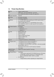
... occur. • Set the CPU host frequency in accordance with the CPU specifications. It is not recommended that the motherboard supports the CPU. (Go to GIGABYTE's website for the peripherals. Hardware Installation 1-3 Installing the CPU and CPU Cooler Read the following guidelines before you begin to install the CPU: • Make... if oriented incorrectly. (Or you wish to set beyond the standard specifications, please do so according to your hardware specifications including the CPU, graphics card, memory, hard drive, etc. 1-3-1 Installing the CPU A.
... occur. • Set the CPU host frequency in accordance with the CPU specifications. It is not recommended that the motherboard supports the CPU. (Go to GIGABYTE's website for the peripherals. Hardware Installation 1-3 Installing the CPU and CPU Cooler Read the following guidelines before you begin to install the CPU: • Make... if oriented incorrectly. (Or you wish to set beyond the standard specifications, please do so according to your hardware specifications including the CPU, graphics card, memory, hard drive, etc. 1-3-1 Installing the CPU A.
Manual
Page 16
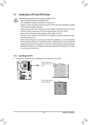
... if only one direction. Dual Channel mode cannot be used . (Go to GIGABYTE's website for optimum performance. DS/SS DS/SS Four Modules DS/SS DS/SS DS/SS DS/SS (SS=Single-Sided, DS=Double-Sided, "- -"=No Memory) DDR3_1 DDR3_2 DDR3_3 DDR3_4 Due to CPU limitations, read the following guidelines before...
... if only one direction. Dual Channel mode cannot be used . (Go to GIGABYTE's website for optimum performance. DS/SS DS/SS Four Modules DS/SS DS/SS DS/SS DS/SS (SS=Single-Sided, DS=Double-Sided, "- -"=No Memory) DDR3_1 DDR3_2 DDR3_3 DDR3_4 Due to CPU limitations, read the following guidelines before...

Manual
Page 17
...the socket will snap into the memory socket. As indicated in the picture on the memory and insert it can only fit in the memory sockets. Place the memory module on this motherboard. Step 2: The clips at both ends of the memory module. Hardware Installation Follow the...at both ends of the memory, push down on the left, place your memory modules in one direction. Notch DDR3 DIMM A DDR3 memory module has a notch, so it vertically into place when the memory module is securely inserted. - 17 - 1-4-2 Installing a Memory Before installing a memory module, make sure to ...
...the socket will snap into the memory socket. As indicated in the picture on the memory and insert it can only fit in the memory sockets. Place the memory module on this motherboard. Step 2: The clips at both ends of the memory module. Hardware Installation Follow the...at both ends of the memory, push down on the left, place your memory modules in one direction. Notch DDR3 DIMM A DDR3 memory module has a notch, so it vertically into place when the memory module is securely inserted. - 17 - 1-4-2 Installing a Memory Before installing a memory module, make sure to ...
Manual
Page 21
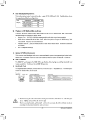
... Port The IEEE 1394 port supports the IEEE 1394a specification, featuring high speed, high bandwidth and hotplug capabilities. The table below . • Memory: Two 1 GB DDR3 1066 MHz memory modules with dual channel mode enabled • BIOS Setup: At least 256 MB of the LAN port LEDs. Before using this port for...
... Port The IEEE 1394 port supports the IEEE 1394a specification, featuring high speed, high bandwidth and hotplug capabilities. The table below . • Memory: Two 1 GB DDR3 1066 MHz memory modules with dual channel mode enabled • BIOS Setup: At least 256 MB of the LAN port LEDs. Before using this port for...

Manual
Page 36
... name (to erase the default profile name, use the SPACE key) and then press to complete. F12: Load CMOS from BIOS If your CPU, memory, etc. Standard CMOS Features Use this menu to configure the system time and date, hard drive types, floppy disk drive types, and the type...
... name (to erase the default profile name, use the SPACE key) and then press to complete. F12: Load CMOS from BIOS If your CPU, memory, etc. Standard CMOS Features Use this menu to configure the system time and date, hard drive types, floppy disk drive types, and the type...

Manual
Page 37
...CPB Ratio (Note) Turbo CPB (Note) CPU Host Clock Control x CPU Frequency(MHz) PCIE Clock(MHz) HT Link Width HT Link Frequency Set Memory Clock x Memory Clock } DRAM Configuration ******** System Voltage Optimized ******** System Voltage Control x DDR3 Voltage control x NorthBridge Volt Control [Press Enter] [Press Enter] [... result in red, it is recommended that you set the System Voltage Control item to Auto to CPU, chipset, or memory and reduce the useful life of these components. This page is for advanced users only and we recommend you install a ...
...CPB Ratio (Note) Turbo CPB (Note) CPU Host Clock Control x CPU Frequency(MHz) PCIE Clock(MHz) HT Link Width HT Link Frequency Set Memory Clock x Memory Clock } DRAM Configuration ******** System Voltage Optimized ******** System Voltage Control x DDR3 Voltage control x NorthBridge Volt Control [Press Enter] [Press Enter] [... result in red, it is recommended that you set the System Voltage Control item to Auto to CPU, chipset, or memory and reduce the useful life of these components. This page is for advanced users only and we recommend you install a ...

Manual
Page 39
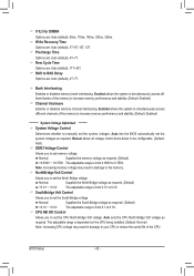
...only if Init Display First under Advanced BIOS Features is set the VGA Core clock. MS-DOS, for example, will use only this memory for the onboard graphics controller. IGX Configuration CMOS Setup Utility-Copyright (C) 1984-2010 Award Software IGX Configuration Internal Graphics Mode UMA Frame ...F6: Fail-Safe Defaults ESC: Exit F1: General Help F7: Optimized Defaults Internal Graphics Mode Allows you to manually set to allocate system memory for output, depending on to 2000 MHz. VGA Core Clock control Allows you to determine whether to manually set the VGA Core clock....
...only if Init Display First under Advanced BIOS Features is set the VGA Core clock. MS-DOS, for example, will use only this memory for the onboard graphics controller. IGX Configuration CMOS Setup Utility-Copyright (C) 1984-2010 Award Software IGX Configuration Internal Graphics Mode UMA Frame ...F6: Fail-Safe Defaults ESC: Exit F1: General Help F7: Optimized Defaults Internal Graphics Mode Allows you to manually set to allocate system memory for output, depending on to 2000 MHz. VGA Core Clock control Allows you to determine whether to manually set the VGA Core clock....

Manual
Page 40
...CPU being installed. (Default: Auto) Turbo CPB (Note) Allows you to determine whether to be configurable. (Default: Auto) Memory Clock This option is configurable only when Set Memory Clock is dependent on the CPU being used . Manual allows the CPU Frequency (MHz) item below to 500 MHz. Auto... reset the board to alter the clock ratio for the installed CPU. PCIE Clock(MHz) Allows you to 150 MHz. Manual allows the memory clock control item below to improve CPU performance. (Default: Disabled) CPU Host Clock Control Enables or disables the control of CPU host clock...
...CPU being installed. (Default: Auto) Turbo CPB (Note) Allows you to determine whether to be configurable. (Default: Auto) Memory Clock This option is configurable only when Set Memory Clock is dependent on the CPU being used . Manual allows the CPU Frequency (MHz) item below to 500 MHz. Auto... reset the board to alter the clock ratio for the installed CPU. PCIE Clock(MHz) Allows you to 150 MHz. Manual allows the memory clock control item below to improve CPU performance. (Default: Disabled) CPU Host Clock Control Enables or disables the control of CPU host clock...
Manual
Page 41
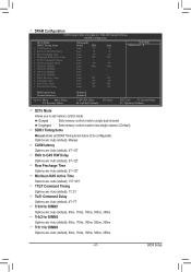
... : Auto (default), 90ns, 110ns, 160ns, 300ns, 350ns. Trfc0 for DIMM3 Options are: Auto (default), 90ns, 110ns, 160ns, 300ns, 350ns. - 41 - Ganged Sets memory control mode to RAS Delay [Unganged] [Auto] SPD Auto 7T Auto 7T Auto 7T Auto 30T Auto -- Options are : Auto (default), 5T~12T. BIOS Setup... ESC: Exit F1: General Help F7: Optimized Defaults DCTs Mode Allows you to be configurable. Auto 5T Auto 90ns Auto -- Unganged Sets memory control mode to two single-channel. (Default) DDR3 Timing Items Manual allows all DDR3 Timing items below to set...
... : Auto (default), 90ns, 110ns, 160ns, 300ns, 350ns. Trfc0 for DIMM3 Options are: Auto (default), 90ns, 110ns, 160ns, 300ns, 350ns. - 41 - Ganged Sets memory control mode to RAS Delay [Unganged] [Auto] SPD Auto 7T Auto 7T Auto 7T Auto 30T Auto -- Options are : Auto (default), 5T~12T. BIOS Setup... ESC: Exit F1: General Help F7: Optimized Defaults DCTs Mode Allows you to be configurable. Auto 5T Auto 90ns Auto -- Unganged Sets memory control mode to two single-channel. (Default) DDR3 Timing Items Manual allows all DDR3 Timing items below to set...
Manual
Page 42
...Control Allows you to manually set the system voltages as required. (Default) +0.050V ~ +0.750V The adjustable range is from 0.050V to set memory voltage. Trfc3 for DIMM4 Options are : Auto (default), 4T~7T. Precharge Time Options are : Auto (default), 90ns, 110ns, 160ns, ... Time Options are: Auto (default), 5T~8T, 10T, 12T. Enabled allows the system to simultaneously access different channels of the memory to increase memory performance and stability. (Default: Enabled) ******** System Voltage Optimized ******** System Voltage Control Determines whether to set the CPU North Bridge...
...Control Allows you to manually set the system voltages as required. (Default) +0.050V ~ +0.750V The adjustable range is from 0.050V to set memory voltage. Trfc3 for DIMM4 Options are : Auto (default), 4T~7T. Precharge Time Options are : Auto (default), 90ns, 110ns, 160ns, ... Time Options are: Auto (default), 5T~8T, 10T, 12T. Enabled allows the system to simultaneously access different channels of the memory to increase memory performance and stability. (Default: Enabled) ******** System Voltage Optimized ******** System Voltage Control Determines whether to set the CPU North Bridge...
Manual
Page 44
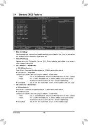
... 3 Master } IDE Channel 3 Slave [None] [None] [None] [None] [None] [None] [None] [None] Drive A Floppy 3 Mode Support [1.44M, 3.5"] [Disabled] Halt On [All, But Keyboard] Base Memory Extended Memory 640K 766M Move Enter: Select F5: Previous Values +/-/PU/PD: Value F10: Save F6: Fail-Safe Defaults ESC: Exit F1: General Help F7: Optimized Defaults...
... 3 Master } IDE Channel 3 Slave [None] [None] [None] [None] [None] [None] [None] [None] Drive A Floppy 3 Mode Support [1.44M, 3.5"] [Disabled] Halt On [All, But Keyboard] Base Memory Extended Memory 640K 766M Move Enter: Select F5: Previous Values +/-/PU/PD: Value F10: Save F6: Fail-Safe Defaults ESC: Exit F1: General Help F7: Optimized Defaults...

Manual
Page 45
... whether the system will stop . Landing Zone Landing zone. Floppy 3 Mode Support Allows you wish to enter the parameters manually, refer to None. Memory These fields are read-only and are : Disabled (default), Drive A. If you do not install a floppy disk drive, set this item to... the information on the hard drive. Base Memory Also called conventional memory. All, But Disk/Key The system boot will not stop for all other errors. Precomp Write precompensation cylinder. Extended...
... whether the system will stop . Landing Zone Landing zone. Floppy 3 Mode Support Allows you wish to enter the parameters manually, refer to None. Memory These fields are read-only and are : Disabled (default), Drive A. If you do not install a floppy disk drive, set this item to... the information on the hard drive. Base Memory Also called conventional memory. All, But Disk/Key The system boot will not stop for all other errors. Precomp Write precompensation cylinder. Extended...

Manual
Page 52
... , power on by mouse, power on by keyboard, and wake on LAN. (Note) Supported on this function, avoid inadequate shutdown from an AC power loss. Memory The system returns to its last known awake state upon the return of the AC power. Press on this function. (Default) Double Click Double click...
... , power on by mouse, power on by keyboard, and wake on LAN. (Note) Supported on this function, avoid inadequate shutdown from an AC power loss. Memory The system returns to its last known awake state upon the return of the AC power. Press on this function. (Default) Double Click Double click...

Manual
Page 63
..., the hard drive on the first IDE connector is the first physical drive. - 63 - Unique Features System Requirements: • At least 512 MB of system memory • VESA compatible graphics card • Windows XP with Xpress Recovery cannot be restored using Xpress Recovery2. • USB hard drives are installed. • The...
..., the hard drive on the first IDE connector is the first physical drive. - 63 - Unique Features System Requirements: • At least 512 MB of system memory • VESA compatible graphics card • Windows XP with Xpress Recovery cannot be restored using Xpress Recovery2. • USB hard drives are installed. • The...
Manual
Page 70
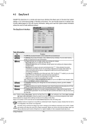
... indicates that allows users to fine-tune their system-related information without the need to install additional software. 4-3 EasyTune 6 GIGABYTE's EasyTune 6 is a simple and easy-to-use interface that the item is not configurable or the function is not supported...doing overclock/overvoltage may occur. The EasyTune 6 Interface Tabs Information Tab Function The CPU tab provides information on the installed memory module(s). After restart, the system will operate with the optimum overclocking configuration after restart. (Note 2) Restart the computer ...
... indicates that allows users to fine-tune their system-related information without the need to install additional software. 4-3 EasyTune 6 GIGABYTE's EasyTune 6 is a simple and easy-to-use interface that the item is not configurable or the function is not supported...doing overclock/overvoltage may occur. The EasyTune 6 Interface Tabs Information Tab Function The CPU tab provides information on the installed memory module(s). After restart, the system will operate with the optimum overclocking configuration after restart. (Note 2) Restart the computer ...


