
Manual
Page 35
...set your system to its defaults. • The BIOS Setup menus described in this chapter are for the menu. BIOS Setup Submenu Help While in a submenu, press to display a help screen. 2-2 The Main Menu Once you want in the Main Menu or a submenu, press + to access more advanced options. &#...Q-Flash Select Item F10: Save & Exit Setup Change CPU's Clock & Voltage F11: Save CMOS to BIOS F12: Load CMOS from BIOS Main Menu Help The on-screen description of a highlighted setup option is not stable as shown below) appears on the right (submenus only) Restore the previous BIOS settings...
...set your system to its defaults. • The BIOS Setup menus described in this chapter are for the menu. BIOS Setup Submenu Help While in a submenu, press to display a help screen. 2-2 The Main Menu Once you want in the Main Menu or a submenu, press + to access more advanced options. &#...Q-Flash Select Item F10: Save & Exit Setup Change CPU's Clock & Voltage F11: Save CMOS to BIOS F12: Load CMOS from BIOS Main Menu Help The on-screen description of a highlighted setup option is not stable as shown below) appears on the right (submenus only) Restore the previous BIOS settings...
Manual
Page 37
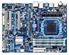
... Vcore [Auto] 2800Mhz [Auto] 2000Mhz [Auto] 200 [Auto] [Disabled] [Auto] 2000Mhz [Auto] x6.66 1333Mhz [Press Enter] [Auto] Auto Auto Auto Auto Auto 1.3250V Item Help Menu Level Move Enter: Select F5: Previous Values +/-/PU/PD: Value F10: Save F6: Fail-Safe Defaults ESC: Exit F1: General...
... Vcore [Auto] 2800Mhz [Auto] 2000Mhz [Auto] 200 [Auto] [Disabled] [Auto] 2000Mhz [Auto] x6.66 1333Mhz [Press Enter] [Auto] Auto Auto Auto Auto Auto 1.3250V Item Help Menu Level Move Enter: Select F5: Previous Values +/-/PU/PD: Value F10: Save F6: Fail-Safe Defaults ESC: Exit F1: General...

Manual
Page 38
...Auto 5T Auto 90ns Auto -- Auto 10T Auto 5T Auto 28T Auto 4T Auto 7T 7T 7T 30T -5T 90ns ---10T 5T 28T 4T Item Help Menu Level Bank interleaving Channel interleave Move Enter: Select F5: Previous Values [Enabled] [Enabled] +/-/PU/PD: Value F10: Save ...F6: Fail-Safe Defaults ESC: Exit F1: General Help F7: Optimized Defaults DCTs Mode Allows you to manually set memory control mode. Auto lets BIOS automatically set the memory clock. X5.33 Sets Memory...
...Auto 5T Auto 90ns Auto -- Auto 10T Auto 5T Auto 28T Auto 4T Auto 7T 7T 7T 30T -5T 90ns ---10T 5T 28T 4T Item Help Menu Level Bank interleaving Channel interleave Move Enter: Select F5: Previous Values [Enabled] [Enabled] +/-/PU/PD: Value F10: Save ...F6: Fail-Safe Defaults ESC: Exit F1: General Help F7: Optimized Defaults DCTs Mode Allows you to manually set memory control mode. Auto lets BIOS automatically set the memory clock. X5.33 Sets Memory...

Manual
Page 41
...Utility-Copyright (C) 1984-2010 Award Software Standard CMOS Features Date (mm:dd:yy) Time (hh:mm:ss) Mon, Dec 20 2010 22:31:24 Item Help Menu Level } IDE Channel 0 Master } IDE Channel 0 Slave } IDE Channel 1 Master } IDE Channel 1 Slave } IDE Channel 2 ...[Disabled] Move Enter: Select F5: Previous Values +/-/PU/PD: Value F10: Save F6: Fail-Safe Defaults ESC: Exit F1: General Help F7: Optimized Defaults CMOS Setup Utility-Copyright (C) 1984-2010 Award Software Standard CMOS Features Halt On Base Memory Extended Memory [All, But Keyboard...
...Utility-Copyright (C) 1984-2010 Award Software Standard CMOS Features Date (mm:dd:yy) Time (hh:mm:ss) Mon, Dec 20 2010 22:31:24 Item Help Menu Level } IDE Channel 0 Master } IDE Channel 0 Slave } IDE Channel 1 Master } IDE Channel 1 Slave } IDE Channel 2 ...[Disabled] Move Enter: Select F5: Previous Values +/-/PU/PD: Value F10: Save F6: Fail-Safe Defaults ESC: Exit F1: General Help F7: Optimized Defaults CMOS Setup Utility-Copyright (C) 1984-2010 Award Software Standard CMOS Features Halt On Base Memory Extended Memory [All, But Keyboard...
Manual
Page 43
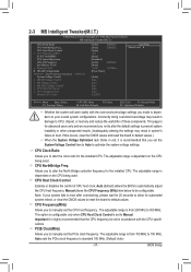
...] [Disabled] [Auto] [Disabled] [Auto] Enabled Enabled Enabled [Press Enter] [Hard Disk] [CDROM] [Floppy] [Setup] [Disabled] [Disabled] [Enabled] [Disabled] [PCI Slot] Item Help Menu Level Move Enter: Select F5: Previous Values +/-/PU/PD: Value F10: Save F6: Fail-Safe Defaults ESC: Exit F1: General... Help F7: Optimized Defaults AMD C1E Support (Note) Enables or disables the C1E CPU power-saving function in independent partitions. Auto Lets the ...
...] [Disabled] [Auto] [Disabled] [Auto] Enabled Enabled Enabled [Press Enter] [Hard Disk] [CDROM] [Floppy] [Setup] [Disabled] [Disabled] [Enabled] [Disabled] [PCI Slot] Item Help Menu Level Move Enter: Select F5: Previous Values +/-/PU/PD: Value F10: Save F6: Fail-Safe Defaults ESC: Exit F1: General... Help F7: Optimized Defaults AMD C1E Support (Note) Enables or disables the C1E CPU power-saving function in independent partitions. Auto Lets the ...
Manual
Page 45
...] IDE Enabled [Enabled] Press Enter [Enabled] [IDE] [Enabled] [IDE] [Enabled] [Disabled] [Press Enter] [Enabled] [Enabled] [Enabled] [Enabled] [Enabled] [Enabled] Item Help Menu Level Move Enter: Select F5: Previous Values +/-/PU/PD: Value F10: Save F6: Fail-Safe Defaults ESC: Exit F1: General... Onboard Serial Port 1 Onboard Parallel Port Parallel Port Mode x ECP Mode Use DMA [3F8/IRQ4] [378/IRQ7] [SPP] 3 Item Help Menu Level Move Enter: Select F5: Previous Values +/-/PU/PD: Value F10: Save F6: Fail-Safe Defaults ESC: Exit F1: General...
...] IDE Enabled [Enabled] Press Enter [Enabled] [IDE] [Enabled] [IDE] [Enabled] [Disabled] [Press Enter] [Enabled] [Enabled] [Enabled] [Enabled] [Enabled] [Enabled] Item Help Menu Level Move Enter: Select F5: Previous Values +/-/PU/PD: Value F10: Save F6: Fail-Safe Defaults ESC: Exit F1: General... Onboard Serial Port 1 Onboard Parallel Port Parallel Port Mode x ECP Mode Use DMA [3F8/IRQ4] [378/IRQ7] [SPP] 3 Item Help Menu Level Move Enter: Select F5: Previous Values +/-/PU/PD: Value F10: Save F6: Fail-Safe Defaults ESC: Exit F1: General...
Manual
Page 46
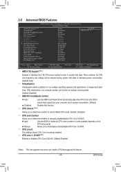
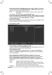
...the connected SATA device. (Default: Disabled) Onboard GSATA/IDE Ctrl (GIGABYTE SATA2 Chip, GSATA2_6/7 Connectors) Enables or disables the SATA controller integrated in the GIGABYTE SATA2 chip. (Default: Enabled) Onboard GSATA/IDE Mode (GIGABYTE SATA2 Chip, GSATA2_6/7 Connectors) Allows you to decide whether to configure... ESP Port3 as ESP x Port4 as ESP x Port5 as ESP [Disabled] [Disabled] [Disabled] [Disabled] Disabled Disabled Item Help Menu Level Move Enter: Select F5: Previous Values +/-/PU/PD: Value F10: Save F6: Fail-Safe Defaults ESC: Exit F1:...
...the connected SATA device. (Default: Disabled) Onboard GSATA/IDE Ctrl (GIGABYTE SATA2 Chip, GSATA2_6/7 Connectors) Enables or disables the SATA controller integrated in the GIGABYTE SATA2 chip. (Default: Enabled) Onboard GSATA/IDE Mode (GIGABYTE SATA2 Chip, GSATA2_6/7 Connectors) Allows you to decide whether to configure... ESP Port3 as ESP x Port4 as ESP x Port5 as ESP [Disabled] [Disabled] [Disabled] [Disabled] Disabled Disabled Item Help Menu Level Move Enter: Select F5: Previous Values +/-/PU/PD: Value F10: Save F6: Fail-Safe Defaults ESC: Exit F1:...
Manual
Page 47
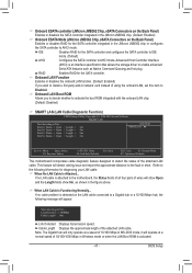
... Part1-2 Status = Open / Length = 0m Part3-6 Status = Open / Length = 0m Part4-5 Status = Open / Length = 0m Part7-8 Status = Open / Length = 0m Item Help Menu Level Move Enter: Select F5: Previous Values +/-/PU/PD: Value F10: Save F6: Fail-Safe Defaults ESC: Exit F1: General... Help F7: Optimized Defaults This motherboard incorporates cable diagnostic feature designed to the motherboard, the Status fields of all four pairs of wires will ...
... Part1-2 Status = Open / Length = 0m Part3-6 Status = Open / Length = 0m Part4-5 Status = Open / Length = 0m Part7-8 Status = Open / Length = 0m Item Help Menu Level Move Enter: Select F5: Previous Values +/-/PU/PD: Value F10: Save F6: Fail-Safe Defaults ESC: Exit F1: General... Help F7: Optimized Defaults This motherboard incorporates cable diagnostic feature designed to the motherboard, the Status fields of all four pairs of wires will ...
Manual
Page 49
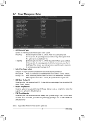
... Setup The system can be turned off ] [Enabled] [Disabled] [Enabled] [Enabled] [Disabled] [Disabled] Enter [Soft-Off] [Disabled] Everyday 0 : 0 : 0 [Disabled] Item Help Menu Level Move Enter: Select F5: Previous Values +/-/PU/PD: Value F10: Save F6: Fail-Safe Defaults ESC: Exit F1: General... Help F7: Optimized Defaults ACPI Suspend Type Specifies the ACPI sleep state when the system enters suspend. Soft-Off by a wake-up signal from...
... Setup The system can be turned off ] [Enabled] [Disabled] [Enabled] [Enabled] [Disabled] [Disabled] Enter [Soft-Off] [Disabled] Everyday 0 : 0 : 0 [Disabled] Item Help Menu Level Move Enter: Select F5: Previous Values +/-/PU/PD: Value F10: Save F6: Fail-Safe Defaults ESC: Exit F1: General... Help F7: Optimized Defaults ACPI Suspend Type Specifies the ACPI sleep state when the system enters suspend. Soft-Off by a wake-up signal from...

Manual
Page 51
...Enabled] [Disabled] No 1.364V 1.536V 3.280V 12.048V 38oC 36oC 1962 RPM 0 RPM 0 RPM 0 RPM [Disabled] [Disabled] [Disabled] [Disabled] [Disabled] [Enabled] Item Help Menu Level Move Enter: Select F5: Previous Values +/-/PU/PD: Value F10: Save F6: Fail-Safe Defaults ESC: Exit F1: General... Move Enter: Select F5: Previous Values +/-/PU/PD: Value F10: Save F6: Fail-Safe Defaults ESC: Exit F1: General Help F7: Optimized Defaults Hardware Thermal Control Enables or disables the CPU overheating protection function. When enabled, the CPU core voltage and ratio will...
...Enabled] [Disabled] No 1.364V 1.536V 3.280V 12.048V 38oC 36oC 1962 RPM 0 RPM 0 RPM 0 RPM [Disabled] [Disabled] [Disabled] [Disabled] [Disabled] [Enabled] Item Help Menu Level Move Enter: Select F5: Previous Values +/-/PU/PD: Value F10: Save F6: Fail-Safe Defaults ESC: Exit F1: General... Move Enter: Select F5: Previous Values +/-/PU/PD: Value F10: Save F6: Fail-Safe Defaults ESC: Exit F1: General Help F7: Optimized Defaults Hardware Thermal Control Enables or disables the CPU overheating protection function. When enabled, the CPU core voltage and ratio will...

Manual
Page 53
... F12: Load CMOS from BIOS Press on this item and then press the key to load the optimal BIOS default settings. The BIOS defaults settings help the system to load the safest BIOS default settings.
... F12: Load CMOS from BIOS Press on this item and then press the key to load the optimal BIOS default settings. The BIOS defaults settings help the system to load the safest BIOS default settings.

Manual
Page 67
... updating the BIOS. Using @BIOS 1. Follow the on the @BIOS server site, please manually download the BIOS update file from GIGABYTE's website and follow the instructions in a corrupted BIOS or a system that matches your system after the system restarts. After Updating ...Internet Update Function" below. 2. Before You Begin 1. In Windows, close all applications and TSR (Terminate and Stay Resident) programs. This helps prevent unexpected failures when performing a BIOS update. 2. Update the BIOS Using the Internet Update Function: Click Update BIOS from File, then...
... updating the BIOS. Using @BIOS 1. Follow the on the @BIOS server site, please manually download the BIOS update file from GIGABYTE's website and follow the instructions in a corrupted BIOS or a system that matches your system after the system restarts. After Updating ...Internet Update Function" below. 2. Before You Begin 1. In Windows, close all applications and TSR (Terminate and Stay Resident) programs. This helps prevent unexpected failures when performing a BIOS update. 2. Update the BIOS Using the Internet Update Function: Click Update BIOS from File, then...
Manual
Page 69
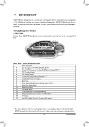
...CPU Power and Power Scores are for reference only. 4-4 Easy Energy Saver GIGABYTE Easy Energy Saver is for reference only. Meter Mode In Meter Mode, GIGABYTE Easy Energy Saver shows how much power they have saved in taskbar) 14 INFO/Help 15 Live Utility Update (Check for the latest utility version) • ...continue to provide exceptional power savings and enhanced power efficiency without sacrificing computing performance. Meter Mode - Unique Features Featuring an advanced proprietary software design, GIGABYTE Easy Energy Saver is able to run in a set period of the button.
...CPU Power and Power Scores are for reference only. 4-4 Easy Energy Saver GIGABYTE Easy Energy Saver is for reference only. Meter Mode In Meter Mode, GIGABYTE Easy Energy Saver shows how much power they have saved in taskbar) 14 INFO/Help 15 Live Utility Update (Check for the latest utility version) • ...continue to provide exceptional power savings and enhanced power efficiency without sacrificing computing performance. Meter Mode - Unique Features Featuring an advanced proprietary software design, GIGABYTE Easy Energy Saver is able to run in a set period of the button.

Manual
Page 70
... able to run in a set period of power saved will continue to see how much total power savings they have accumulated in taskbar) 13 INFO/Help 14 Live Utility Update (Check for the first time (Note 3). Total Mode -
... able to run in a set period of power saved will continue to see how much total power savings they have accumulated in taskbar) 13 INFO/Help 14 Live Utility Update (Check for the first time (Note 3). Total Mode -

Manual
Page 76
... Port 1 [Enabled] [RAID] [As SATA Type] [Enabled] [Enabled] [Enabled] [IDE] [Enabled] [IDE] [Enabled] [Disabled] [Press Enter] [Enabled] [Enabled] [Enabled] [Enabled] [Enabled] [Enabled] [3F8/IRQ4] Item Help Menu Level Move Enter: Select F5: Previous Values +/-/PU/PD: Value F10: Save F6: Fail-Safe Defaults ESC: Exit F1: General...
... Port 1 [Enabled] [RAID] [As SATA Type] [Enabled] [Enabled] [Enabled] [IDE] [Enabled] [IDE] [Enabled] [Disabled] [Press Enter] [Enabled] [Enabled] [Enabled] [Enabled] [Enabled] [Enabled] [3F8/IRQ4] Item Help Menu Level Move Enter: Select F5: Previous Values +/-/PU/PD: Value F10: Save F6: Fail-Safe Defaults ESC: Exit F1: General...
Manual
Page 81
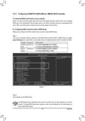
... Appendix Then connect the power connector from the exact settings for the SATA controllers and their corresponding SATA ports. B. 5-1-2 Configuring GIGABYTE SATA2/JMicron JMB362 SATA Controller A. In BIOS Setup, go to RAID CMOS Setup Utility-Copyright (C) 1984-2010 Award Software Integrated ...] [Enabled] [RAID/IDE] [Enabled] [RAID] [Enabled] [Disabled] [Press Enter] [Enabled] [Enabled] [Enabled] [Enabled] [Enabled] [Enabled] [3F8/IRQ4] Item Help Menu Level Move Enter: Select F5: Previous Values +/-/PU/PD: Value F10: Save F6: Fail-Safe Defaults ESC: Exit F1: General...
... Appendix Then connect the power connector from the exact settings for the SATA controllers and their corresponding SATA ports. B. 5-1-2 Configuring GIGABYTE SATA2/JMicron JMB362 SATA Controller A. In BIOS Setup, go to RAID CMOS Setup Utility-Copyright (C) 1984-2010 Award Software Integrated ...] [Enabled] [RAID/IDE] [Enabled] [RAID] [Enabled] [Disabled] [Press Enter] [Enabled] [Enabled] [Enabled] [Enabled] [Enabled] [Enabled] [3F8/IRQ4] Item Help Menu Level Move Enter: Select F5: Previous Values +/-/PU/PD: Value F10: Save F6: Fail-Safe Defaults ESC: Exit F1: General...
Manual
Page 83
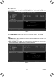
...Appendix Steps: 1. Select RAID Mode: Under the Level item, use up or down arrow key to be special characters) and press . 2. Gigabyte Technology Corp. Enter Array Name: Under the Name item, enter an array name with 1~16 letters (letters cannot be set for huge temporarily ...HDD0: ST3120026AS HDD1: ST3120026AS Available 120 GB 120 GB Type/Status Non-RAID Non-RAID Confirm Creation [ RAID Disk Drive List ] [ Help ] Select RAID Level RAID 0 RAID 1 JBOD Data striped for performance Data mirrored for redundancy Data concatenated for creating an array (Figure ...
...Appendix Steps: 1. Select RAID Mode: Under the Level item, use up or down arrow key to be special characters) and press . 2. Gigabyte Technology Corp. Enter Array Name: Under the Name item, enter an array name with 1~16 letters (letters cannot be set for huge temporarily ...HDD0: ST3120026AS HDD1: ST3120026AS Available 120 GB 120 GB Type/Status Non-RAID Non-RAID Confirm Creation [ RAID Disk Drive List ] [ Help ] Select RAID Level RAID 0 RAID 1 JBOD Data striped for performance Data mirrored for redundancy Data concatenated for creating an array (Figure ...
Manual
Page 84
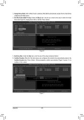
3. Gigabyte Technology Corp. The following are configured, the selection bar automatically jumps to 128 KB. Confirm Creation: After all of the array...} HDD0: ST3120026AS } HDD1: ST3120026AS Available 120 GB 120 GB Type/Status Non-RAID Non-RAID Confirm Creation [ RAID Disk Drive List ] [ Help ] Setting Stripe Block Select a stripe size which will be used to divide data from 4 KB to the Confirm Creation item. When prompted to ... from /to abort. [ Create New RAID ] Name: Level: Disks: Block: Size: GRAID 0-Stripe Select Disk 128 KB 240 GB Gigabyte Technology Corp.
3. Gigabyte Technology Corp. The following are configured, the selection bar automatically jumps to 128 KB. Confirm Creation: After all of the array...} HDD0: ST3120026AS } HDD1: ST3120026AS Available 120 GB 120 GB Type/Status Non-RAID Non-RAID Confirm Creation [ RAID Disk Drive List ] [ Help ] Setting Stripe Block Select a stripe size which will be used to divide data from 4 KB to the Confirm Creation item. When prompted to ... from /to abort. [ Create New RAID ] Name: Level: Disks: Block: Size: GRAID 0-Stripe Select Disk 128 KB 240 GB Gigabyte Technology Corp.
Manual
Page 106
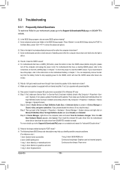
... or Unknown device is still on. When the Add New Hardware Wizard appears, click Cancel. A: The following Award BIOS beep code descriptions may help you identify possible computer problems. (For reference only.) 1 short: System boots successfully 1 long, 9 short: BIOS ROM error 2 short: ...Support & Downloads\FAQ page on after the computer shuts down ? A: Some motherboards provide a small amount of my keyboard/optical mouse still on GIGABYTE's website. Q: Why is equipped with power/amplifier. Then make sure Service Pack 1 or Service Pack 2 has been installed (check in Device...
... or Unknown device is still on. When the Add New Hardware Wizard appears, click Cancel. A: The following Award BIOS beep code descriptions may help you identify possible computer problems. (For reference only.) 1 short: System boots successfully 1 long, 9 short: BIOS ROM error 2 short: ...Support & Downloads\FAQ page on after the computer shuts down ? A: Some motherboards provide a small amount of my keyboard/optical mouse still on GIGABYTE's website. Q: Why is equipped with power/amplifier. Then make sure Service Pack 1 or Service Pack 2 has been installed (check in Device...

Manual
Page 108
... one (install one device at one time and then boot the system to submit your problem, contact the place of purchase or local dealer for help. Or go to the Support & Downloads\Technical Support page to see if the device works successfully). No The IDE/SATA device, connector, or cable might...
... one (install one device at one time and then boot the system to submit your problem, contact the place of purchase or local dealer for help. Or go to the Support & Downloads\Technical Support page to see if the device works successfully). No The IDE/SATA device, connector, or cable might...


