
Manual
Page 1
GA-5YASV-RH Xeon® Processor Motherboard USER'S MANUAL Xeon® Processor Motherboard Rev. 1001 * The WEEE marking on the product indicates this product must not be disposed of with user's other household waste and must be handed over to a designated collection point for the recycling of waste electrical and electronic equipment!! * The WEEE marking applies only in European Union's member states.
GA-5YASV-RH Xeon® Processor Motherboard USER'S MANUAL Xeon® Processor Motherboard Rev. 1001 * The WEEE marking on the product indicates this product must not be disposed of with user's other household waste and must be handed over to a designated collection point for the recycling of waste electrical and electronic equipment!! * The WEEE marking applies only in European Union's member states.

Manual
Page 2
... of Content Item Checklist 4 WARNING 4 Chapter 1 Introduction 5 1.1 Features Summary 5 1.2 GA-5YASV-RH Motherboard Components 8 Chapter 2 Hardware Installation Process 10 2-1: Installing Processor and CPU Haet Sink 10 2-1-1: Installing CPU ...10 2-1-2: Installing Cooling Fan 11 2-2: Install Memory Modules 12 2-3: Connect ...
... of Content Item Checklist 4 WARNING 4 Chapter 1 Introduction 5 1.1 Features Summary 5 1.2 GA-5YASV-RH Motherboard Components 8 Chapter 2 Hardware Installation Process 10 2-1: Installing Processor and CPU Haet Sink 10 2-1-1: Installing CPU ...10 2-1-2: Installing Cooling Fan 11 2-2: Install Memory Modules 12 2-3: Connect ...

Manual
Page 4
...GA-5YASV-RH Motherboard Item Checklist The GA-5YASV-RH motherboard IDE (ATA133 ) cable x 1 / Floppy cable x 1 CD for motherboard driver & utility USB cable x 1 Serial ATA cable x 6 I/O Shield Kit SATA Power cable x 3 Ga-5YASV-RH Quick Reference Guide WARNING! Installing the motherboard to a metal object, such as the power supply case. 3. If the motherboard... that are separated from static electricity, you should follow some precautions whenever you can still attach the motherboard to the mounting holes. Use a grounded wrist strap before you can still attach the spacers to ...
...GA-5YASV-RH Motherboard Item Checklist The GA-5YASV-RH motherboard IDE (ATA133 ) cable x 1 / Floppy cable x 1 CD for motherboard driver & utility USB cable x 1 Serial ATA cable x 6 I/O Shield Kit SATA Power cable x 3 Ga-5YASV-RH Quick Reference Guide WARNING! Installing the motherboard to a metal object, such as the power supply case. 3. If the motherboard... that are separated from static electricity, you should follow some precautions whenever you can still attach the motherboard to the mounting holes. Use a grounded wrist strap before you can still attach the spacers to ...

Manual
Page 6
English GA-5YASV-RH Motherboard Hardware Monitor On-Board LAN BIOS Special Features Additional Features Enhanced features with CPU Vcore, 1.2V reference, VCC3 (3.3V) , VBAT3V, +5VSB, CPU Temperature, and System ...
English GA-5YASV-RH Motherboard Hardware Monitor On-Board LAN BIOS Special Features Additional Features Enhanced features with CPU Vcore, 1.2V reference, VCC3 (3.3V) , VBAT3V, +5VSB, CPU Temperature, and System ...

Manual
Page 8
... cable connector 22. PCI-E x8 Slot 28. DDR2A1 30. Parallel Port 36. Battery 39. 24-pin ATX power connector 40. 8-pin ATX power connector 8 English GA-5YASV-RH Motherboard 1.2 GA-5YASV-RH Motherboard Components 1. XGI Volari Z9s 5. SATA1 Connector 16. Intel 82566DM GbE 9. Rear fan cable connector 24. VGA Port 35. SAMSUNG DDR2 6. IDE cable connector 10. SATA0...
... cable connector 22. PCI-E x8 Slot 28. DDR2A1 30. Parallel Port 36. Battery 39. 24-pin ATX power connector 40. 8-pin ATX power connector 8 English GA-5YASV-RH Motherboard 1.2 GA-5YASV-RH Motherboard Components 1. XGI Volari Z9s 5. SATA1 Connector 16. Intel 82566DM GbE 9. Rear fan cable connector 24. VGA Port 35. SAMSUNG DDR2 6. IDE cable connector 10. SATA0...

Manual
Page 10
English GA-5YASV-RH Motherboard Chapter 2 Hardware Installation Process 2-1: Installing Processor and CPU Haet Sink Before installing the processor and cooling fan, adhere to the following cautions: 1. Never force the ... socket Pin 1 and CPU cut edge well, it may damage the CPU. Step 3 Lift the metal cover. Step 5 Once the CPU is supported by the motherboard. 5. Step 2 Remove the plastic covering on the socket. The CPU only fits in permanent irreparable damage. 2. Please change the insert orientation. 2-1-1: Installing CPU Step 1 Raise...
English GA-5YASV-RH Motherboard Chapter 2 Hardware Installation Process 2-1: Installing Processor and CPU Haet Sink Before installing the processor and cooling fan, adhere to the following cautions: 1. Never force the ... socket Pin 1 and CPU cut edge well, it may damage the CPU. Step 3 Lift the metal cover. Step 5 Once the CPU is supported by the motherboard. 5. Step 2 Remove the plastic covering on the socket. The CPU only fits in permanent irreparable damage. 2. Please change the insert orientation. 2-1-1: Installing CPU Step 1 Raise...

Manual
Page 12
It supports Dual Channels Technology. For detail DIMM installation, please refer to the following instructions. The BIOS will automatically detects memory type and size during system boot. English GA-5YASV-RH Motherboard 2-2: Install Memory Modules Before installing the processor and heatsink, adhere to the following warning: When DIMM LED is ON, do not install/remove DIMM from socket. GA-5YASV-RH has 4 dual inline memory module (DIMM) sokcets. Channel B 12 Channel A
It supports Dual Channels Technology. For detail DIMM installation, please refer to the following instructions. The BIOS will automatically detects memory type and size during system boot. English GA-5YASV-RH Motherboard 2-2: Install Memory Modules Before installing the processor and heatsink, adhere to the following warning: When DIMM LED is ON, do not install/remove DIMM from socket. GA-5YASV-RH has 4 dual inline memory module (DIMM) sokcets. Channel B 12 Channel A

Manual
Page 14
English GA-5YASV-RH Motherboard 2-3: Connect ribbon cables, cabinet wires, and power supply 2-3-1 : I/O Back Panel Introduction 14
English GA-5YASV-RH Motherboard 2-3: Connect ribbon cables, cabinet wires, and power supply 2-3-1 : I/O Back Panel Introduction 14

Manual
Page 16
... 12. CPU_FAN 16. REAR_FAN 19. ATX1 2. FDC1 (Floppy cable connector) 5. SATA 5 (SATA cable connector) 11. BAT1 (Battery) 16 F_Panel (Front Panel connector) 20. ATX2 3. English GA-5YASV-RH Motherboard 2-4: Connectors Introduction 18 16 2 15 11 20 12 13 14 10 8 6 17 9 7 19 5 4 3 1 1. SATA 2 (SATA cable connector) 8. F_USB2 (USB cable connector) 14. SYS_FAN 17...
... 12. CPU_FAN 16. REAR_FAN 19. ATX1 2. FDC1 (Floppy cable connector) 5. SATA 5 (SATA cable connector) 11. BAT1 (Battery) 16 F_Panel (Front Panel connector) 20. ATX2 3. English GA-5YASV-RH Motherboard 2-4: Connectors Introduction 18 16 2 15 11 20 12 13 14 10 8 6 17 9 7 19 5 4 3 1 1. SATA 2 (SATA cable connector) 8. F_USB2 (USB cable connector) 14. SYS_FAN 17...

Manual
Page 18
It supports 720K,1.2M,1.44M and 2.88Mbytes floppy disk types. The red stripe of the ribbon cable must be the same side with the Pin1. 1 33 2 34 18 The red stripe of the ribbon cable must be the same side with the Pin1. 39 40 1 2 4 ) FDC1 (Floppy Connector) Please connect the floppy drive ribbon cables to IDE1. English GA-5YASV-RH Motherboard 3 ) IDE1 (IDE Connector) Please connect first harddisk to FDD.
It supports 720K,1.2M,1.44M and 2.88Mbytes floppy disk types. The red stripe of the ribbon cable must be the same side with the Pin1. 1 33 2 34 18 The red stripe of the ribbon cable must be the same side with the Pin1. 39 40 1 2 4 ) FDC1 (Floppy Connector) Please connect the floppy drive ribbon cables to IDE1. English GA-5YASV-RH Motherboard 3 ) IDE1 (IDE Connector) Please connect first harddisk to FDD.

Manual
Page 20
English GA-5YASV-RH Motherboard 12/ 13 ) F_USB1/2 (USB cable connectors) Be careful with Hard disk drives (HDDs) to work or even damage it. Definition 1 No Pin 12 2 NC 3 GND 4 ...
English GA-5YASV-RH Motherboard 12/ 13 ) F_USB1/2 (USB cable connectors) Be careful with Hard disk drives (HDDs) to work or even damage it. Definition 1 No Pin 12 2 NC 3 GND 4 ...

Manual
Page 22
... connect No connect No connect No connect Pin Removed LAN access LED Signal cathode(-) No connect LAN access LED Signal anode (+) No connect 22 English GA-5YASV-RH Motherboard 16 ) F_Panel (2X12 Pins Front Panel connector) Please connect the power LED, PC speaker, reset switch and power switch of your chassis front panel to...
... connect No connect No connect No connect Pin Removed LAN access LED Signal cathode(-) No connect LAN access LED Signal anode (+) No connect 22 English GA-5YASV-RH Motherboard 16 ) F_Panel (2X12 Pins Front Panel connector) Please connect the power LED, PC speaker, reset switch and power switch of your chassis front panel to...

Manual
Page 23
CAUTION Danger of used batteries according to erase CMOS... 1.Turn OFF the computer and unplug the power cord. 2.Remove the battery, wait for 30 second. 3.Re-install the battery. 4.Plug the power cord and turn ON the computer. Replace only with the same or equivalent type recommended by the manufacturer. English GA-5YASV-RH Motherboard 17 ) Battery If you want to the manufacturer's instructions. 23 Dispose of explosion if battery is incorrectly replaced.
CAUTION Danger of used batteries according to erase CMOS... 1.Turn OFF the computer and unplug the power cord. 2.Remove the battery, wait for 30 second. 3.Re-install the battery. 4.Plug the power cord and turn ON the computer. Replace only with the same or equivalent type recommended by the manufacturer. English GA-5YASV-RH Motherboard 17 ) Battery If you want to the manufacturer's instructions. 23 Dispose of explosion if battery is incorrectly replaced.

Manual
Page 24
MODEL_1 8. MODEL_2 9. PASSWORD1 24 PWR_JP1 3. PWR_JP5 5 6 8 10 79 6. MODEL_0 7. RECOVERY1 10. PWR_JP2 4. CLR_CMOS 2. English GA-5YASV-RH Motherboard 2-5: Jumper Setting 2 4 3 1 1. PWR_JP3 5.
MODEL_1 8. MODEL_2 9. PASSWORD1 24 PWR_JP1 3. PWR_JP5 5 6 8 10 79 6. MODEL_0 7. RECOVERY1 10. PWR_JP2 4. CLR_CMOS 2. English GA-5YASV-RH Motherboard 2-5: Jumper Setting 2 4 3 1 1. PWR_JP3 5.
Manual
Page 26
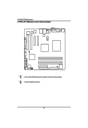
GA-5YASV-RH Motherboard 2 ) PWR_JP1 (USB power source selection jumper) English 1 1-2 close: Rear USB powered when system shut down (Default setting) 1 2-3 close: Disable this function 26
GA-5YASV-RH Motherboard 2 ) PWR_JP1 (USB power source selection jumper) English 1 1-2 close: Rear USB powered when system shut down (Default setting) 1 2-3 close: Disable this function 26

Manual
Page 28
English GA-5YASV-RH Motherboard 4 ) PWR_JP3 (USB1 power source selection jumper) 1 1-2 close: Front USB1 powered when system shut down. (Default setting) 1 2-3 close: Disable this function. 28
English GA-5YASV-RH Motherboard 4 ) PWR_JP3 (USB1 power source selection jumper) 1 1-2 close: Front USB1 powered when system shut down. (Default setting) 1 2-3 close: Disable this function. 28

Manual
Page 31
GA-5YASV-RH Motherboard 9 ) RECCOVERY1 ( BIOS recovery jumper) English 1 1-2 Close: Enable BIOS Recovery function. 1 2-3 Close: Normal (Default setting) 31
GA-5YASV-RH Motherboard 9 ) RECCOVERY1 ( BIOS recovery jumper) English 1 1-2 Close: Enable BIOS Recovery function. 1 2-3 Close: Normal (Default setting) 31

Manual
Page 32
English GA-5YASV-RH Motherboard 10 ) PASSWORD1 (Skip password jumper) 1 1-2 Close: Skip Supervisor Password in BIOS setup menu 1 2-3 Close: Normal (Default setting) 32
English GA-5YASV-RH Motherboard 10 ) PASSWORD1 (Skip password jumper) 1 1-2 Close: Skip Supervisor Password in BIOS setup menu 1 2-3 Close: Normal (Default setting) 32

Manual
Page 34
... BIOS Setup Program. CONTROL KEYS Move to previous item Move to next item Move to the item in the left hand Move to enter Setup. GA-5YASV-RH Motherboard Chapter 3 BIOS Setup BIOS Setup is an overview of information is turned off. Exit current page and return to modify the basic system configuration. ENTERINGSETUP...
... BIOS Setup Program. CONTROL KEYS Move to previous item Move to next item Move to the item in the left hand Move to enter Setup. GA-5YASV-RH Motherboard Chapter 3 BIOS Setup BIOS Setup is an overview of information is turned off. Exit current page and return to modify the basic system configuration. ENTERINGSETUP...

Manual
Page 36
Set the System Time (HH:MM:SS) System Date Set the System Date. Note that the "Day" automatically changed after you enter Phoenix BIOS Setup Utility, the Main Menu (Figure 1) will appear on the 24-hour military time clock. Use arrow keys to select among the items and press to accept or enter the sub-menu. GA-5YASV-RH Motherboard Main Once you set the date. (Weekend: DD: MM: YY) (YY: 1099~2099) 36 Figure 1: Main System Time The time is calculated based on the screen.
Set the System Time (HH:MM:SS) System Date Set the System Date. Note that the "Day" automatically changed after you enter Phoenix BIOS Setup Utility, the Main Menu (Figure 1) will appear on the 24-hour military time clock. Use arrow keys to select among the items and press to accept or enter the sub-menu. GA-5YASV-RH Motherboard Main Once you set the date. (Weekend: DD: MM: YY) (YY: 1099~2099) 36 Figure 1: Main System Time The time is calculated based on the screen.


