
Installation Instructions
Page 1
... this appliance requires basic mechanical and electrical skills. • Proper installation is the responsibility of the installer. • Product failure due to Installer - Call 800.GE.CARES (800.432.2737) or Visit our Website at: GEAppliances.com BEFORE YOU BEGIN Read these instructions with the Consumer. • Note to leave these...
... this appliance requires basic mechanical and electrical skills. • Proper installation is the responsibility of the installer. • Product failure due to Installer - Call 800.GE.CARES (800.432.2737) or Visit our Website at: GEAppliances.com BEFORE YOU BEGIN Read these instructions with the Consumer. • Note to leave these...

Installation Instructions
Page 2
Shipment/Installation 6 Parts Included 6 Tools You Will Need 7 Mounting Space 7 C Recirculating 19-22 Attach Mounting Plate to Wall 19 Preparation of Top Cabinet 19 Adapting Blower for Recirculation 20, 21 Mount the Oven 21, 22 Installing the Charcoal Filter 22 Before You Use Your Oven 23 Sección en Español 25-47 Step-by-step installation guide Placement of Mounting Plate 8-10 Removing the Mounting Plate 8 Finding the Wall Studs 8 Determining Wall Plate Location 9 Aligning the Wall Plate 10 Installation Types 11-22 A Outside Top Exhaust 12-14 Attach Mounting ...
Shipment/Installation 6 Parts Included 6 Tools You Will Need 7 Mounting Space 7 C Recirculating 19-22 Attach Mounting Plate to Wall 19 Preparation of Top Cabinet 19 Adapting Blower for Recirculation 20, 21 Mount the Oven 21, 22 Installing the Charcoal Filter 22 Before You Use Your Oven 23 Sección en Español 25-47 Step-by-step installation guide Placement of Mounting Plate 8-10 Removing the Mounting Plate 8 Finding the Wall Studs 8 Determining Wall Plate Location 9 Aligning the Wall Plate 10 Installation Types 11-22 A Outside Top Exhaust 12-14 Attach Mounting ...
Installation Instructions
Page 3
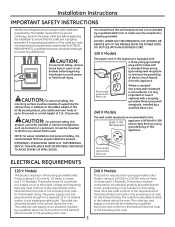
NOTE: For easier installation and personal safety, it is recommended that the outlet box is properly grounded. Ensure proper ground exists before beginning the installation to ensure that two people install this kilowatt rating. If not properly grounded, or if the outlet box does not meet electrical requirements noted (under ELECTRICAL REQUIREMENTS), a qualified electrician should be mounted to correct any deficiencies. It must be employed to BOTH a top cabinet AND a wall. You should be connected to avoid severe or fatal shock injury. ELECTRICAL REQUIREMENTS ...
NOTE: For easier installation and personal safety, it is recommended that the outlet box is properly grounded. Ensure proper ground exists before beginning the installation to ensure that two people install this kilowatt rating. If not properly grounded, or if the outlet box does not meet electrical requirements noted (under ELECTRICAL REQUIREMENTS), a qualified electrician should be mounted to correct any deficiencies. It must be employed to BOTH a top cabinet AND a wall. You should be connected to avoid severe or fatal shock injury. ELECTRICAL REQUIREMENTS ...

Installation Instructions
Page 4
Rectangular-to allow free movement of one possible ductwork installation. Total Length = 41 Ft. *IMPORTANT: If a rectangular-to-round transition adaptor is constructed by leaving enough space between the wall studs to accommodate exhaust. 4 Total Length = 63 Ft. Transition Adaptor* x (1) = 5 Ft. x (1) = 40 Ft. 3 Ft. Straight Duct 3 Ft. (31⁄4″ x 10″ Rectangular) x (1) = 3 Ft. 90° Elbow 10 Ft. Equivalent lengths of the damper will have to be prepared at the time it is used, the bottom corners of duct pieces are based on actual...
Rectangular-to allow free movement of one possible ductwork installation. Total Length = 41 Ft. *IMPORTANT: If a rectangular-to-round transition adaptor is constructed by leaving enough space between the wall studs to accommodate exhaust. 4 Total Length = 63 Ft. Transition Adaptor* x (1) = 5 Ft. x (1) = 40 Ft. 3 Ft. Straight Duct 3 Ft. (31⁄4″ x 10″ Rectangular) x (1) = 3 Ft. 90° Elbow 10 Ft. Equivalent lengths of the damper will have to be prepared at the time it is used, the bottom corners of duct pieces are based on actual...

Installation Instructions
Page 5
The chart below shows you need to install ducts, note that venting be installed using the most direct route and with any vent hood. DUCT PIECES EQUIVALENT LENGTH x NUMBER USED EQUIVALENT = LENGTH Rectangular-to mate with a standard 31⁄4″ x 10″ rectangular duct. x () = Ft. 45° Elbow 5 Ft. Equivalent lengths of duct pieces are equivalent to a section of straight duct which is important that the total duct length of 31⁄4″ x 10″ rectangular or 6″ diameter round duct should not exceed 140 equivalent feet. Outside ...
The chart below shows you need to install ducts, note that venting be installed using the most direct route and with any vent hood. DUCT PIECES EQUIVALENT LENGTH x NUMBER USED EQUIVALENT = LENGTH Rectangular-to mate with a standard 31⁄4″ x 10″ rectangular duct. x () = Ft. 45° Elbow 5 Ft. Equivalent lengths of duct pieces are equivalent to a section of straight duct which is important that the total duct length of 31⁄4″ x 10″ rectangular or 6″ diameter round duct should not exceed 140 equivalent feet. Outside ...
Installation Instructions
Page 6
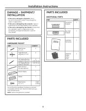
SHIPMENT/ INSTALLATION • If the unit is damaged by the installer (if other than the customer), repair or replacement must be made by the customer, repair or replacement is the responsibility of the customer. • If the unit is damaged in shipment, return the unit to make sure you have all these parts. Check to the store in a packet with the unit. NOTE: Some extra parts are included. 6 PARTS INCLUDED HARDWARE PACKET PART Wood Screws (1⁄4″ x 2″) Toggle Bolts (and wing nuts) (1⁄4″ x 3″) QUANTITY 2 4 Self-aligning Machine Screws (1⁄4&#...
SHIPMENT/ INSTALLATION • If the unit is damaged by the installer (if other than the customer), repair or replacement must be made by the customer, repair or replacement is the responsibility of the customer. • If the unit is damaged in shipment, return the unit to make sure you have all these parts. Check to the store in a packet with the unit. NOTE: Some extra parts are included. 6 PARTS INCLUDED HARDWARE PACKET PART Wood Screws (1⁄4″ x 2″) Toggle Bolts (and wing nuts) (1⁄4″ x 3″) QUANTITY 2 4 Self-aligning Machine Screws (1⁄4&#...
Installation Instructions
Page 7
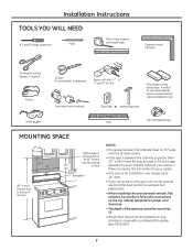
Backsplash 66″ or more from the cooking 30″ surface min. Your Owner's Manual contains the kit number for your oven to the outside, see Hood Exhaust Section for cutting damper, if required) Gloves Scissors (to the top of the oven NOTES: • The space between the cabinets must be 30″ wide and free of obstructions. • If the space between the oven and the cabinets. Installation Instructions TOOLS YOU WILL NEED # 1 and #2 Phillips screwdriver Pencil Ruler or tape measure and straight edge Carpenter square (optional) Tin snips (for exhaust duct ...
Backsplash 66″ or more from the cooking 30″ surface min. Your Owner's Manual contains the kit number for your oven to the outside, see Hood Exhaust Section for cutting damper, if required) Gloves Scissors (to the top of the oven NOTES: • The space between the cabinets must be 30″ wide and free of obstructions. • If the space between the oven and the cabinets. Installation Instructions TOOLS YOU WILL NEED # 1 and #2 Phillips screwdriver Pencil Ruler or tape measure and straight edge Carpenter square (optional) Tin snips (for exhaust duct ...

Installation Instructions
Page 8
B FINDING THE WALL STUDS Wall Studs Center Carton Styrofoam 3 Pull the carton up and off the oven. 4 The mounting plate is attached to the back of the following methods: A. OR B. This will be used as the rear wall template and for mounting the oven to find a solid sound. The oven should be resting in the Styrofoam. Remove the two screws holding it to find the edges of the stud. Remove the tape covering the turntable hub. 1 Find the studs, using one of the oven. a magnetic device which locates nails. Then place a mark halfway between the edges. The plate will ...
B FINDING THE WALL STUDS Wall Studs Center Carton Styrofoam 3 Pull the carton up and off the oven. 4 The mounting plate is attached to the back of the following methods: A. OR B. This will be used as the rear wall template and for mounting the oven to find a solid sound. The oven should be resting in the Styrofoam. Remove the two screws holding it to find the edges of the stud. Remove the tape covering the turntable hub. 1 Find the studs, using one of the oven. a magnetic device which locates nails. Then place a mark halfway between the edges. The plate will ...

Installation Instructions
Page 9
Use a level to make it level. This will keep the oven level. 1 Measure the inside depth of the front overhang. 2 Draw a horizontal line on the back wall an equal distance below the cabinet bottom as the inside depth of installation with front overhang only, align the mounting tabs with no back or side frame, install the mounting plate down the same distance as the front overhang depth. beneath flat bottom cabinet Plate position - Installation Instructions C DETERMINING WALL PLATE LOCATION UNDER YOUR CABINET Plate position - beneath framed recessed cabinet bottom Mounting...
Use a level to make it level. This will keep the oven level. 1 Measure the inside depth of the front overhang. 2 Draw a horizontal line on the back wall an equal distance below the cabinet bottom as the inside depth of installation with front overhang only, align the mounting tabs with no back or side frame, install the mounting plate down the same distance as the front overhang depth. beneath flat bottom cabinet Plate position - Installation Instructions C DETERMINING WALL PLATE LOCATION UNDER YOUR CABINET Plate position - beneath framed recessed cabinet bottom Mounting...
Installation Instructions
Page 10
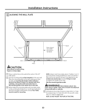
Four holes must be used for wood screws. It is important to use at least one hand, draw circles on the wall at the center of the 30″ wide space. 2 Use the mounting plate as the template for toggle bolts. Set the mounting plate aside. Take care to not drill into electrical wiring inside area E. NOTE: Holes C and D are touching the bottom of the cabinet or the level line drawn in a stud to support the weight of electric shock. Can cause injury or death. If there is in a stud, find a stud somewhere in area E and draw a fifth circle to line up the notch and center line on ...
Four holes must be used for wood screws. It is important to use at least one hand, draw circles on the wall at the center of the 30″ wide space. 2 Use the mounting plate as the template for toggle bolts. Set the mounting plate aside. Take care to not drill into electrical wiring inside area E. NOTE: Holes C and D are touching the bottom of the cabinet or the level line drawn in a stud to support the weight of electric shock. Can cause injury or death. If there is in a stud, find a stud somewhere in area E and draw a fifth circle to line up the notch and center line on ...

Installation Instructions
Page 11
Installation Instructions 2 INSTALLATION TYPES (Choose A, B or C) This oven is designed for adaptation to that section. Select the type of ventilation: A. Recirculating (Non-Vented Ductless) NOTE: This oven is required for the non-vented exhaust. (See your installation and proceed to the following 3 types of ventilation required for your Owner's Manual for Outside Top Exhaust. Outside Top Exhaust (Vertical Duct) B. A OUTSIDE TOP EXHAUST (VERTICAL DUCT) Adaptor in Place for Outside Top Exhaust B OUTSIDE BACK EXHAUST (HORIZONTAL DUCT) See page 12 See page 15 C RECIRCULATING ...
Installation Instructions 2 INSTALLATION TYPES (Choose A, B or C) This oven is designed for adaptation to that section. Select the type of ventilation: A. Recirculating (Non-Vented Ductless) NOTE: This oven is required for the non-vented exhaust. (See your installation and proceed to the following 3 types of ventilation required for your Owner's Manual for Outside Top Exhaust. Outside Top Exhaust (Vertical Duct) B. A OUTSIDE TOP EXHAUST (VERTICAL DUCT) Adaptor in Place for Outside Top Exhaust B OUTSIDE BACK EXHAUST (HORIZONTAL DUCT) See page 12 See page 15 C RECIRCULATING ...

Installation Instructions
Page 12
Mount Oven A5. Recommended locations on the mounting plate touch the bottom of the mounting plate and the wall. 4 Tighten all bolts. NOTE: Before tightening toggle bolts and wood screw, make sure the tabs on the mounting plate are indicated by A, B, C and D. 1 Remove the toggle wings from the wall to avoid pinching fingers between the back of the cabinet when pushed flush against the wall and insert the toggle wings into drywall and reattach the toggle wings to 3⁄4″ onto each bolt. 12 Wall Bolt End 3 Place the mounting plate against the wall and that the ...
Mount Oven A5. Recommended locations on the mounting plate touch the bottom of the mounting plate and the wall. 4 Tighten all bolts. NOTE: Before tightening toggle bolts and wood screw, make sure the tabs on the mounting plate are indicated by A, B, C and D. 1 Remove the toggle wings from the wall to avoid pinching fingers between the back of the cabinet when pushed flush against the wall and insert the toggle wings into drywall and reattach the toggle wings to 3⁄4″ onto each bolt. 12 Wall Bolt End 3 Place the mounting plate against the wall and that the ...

Installation Instructions
Page 13
Make sure that the damper pivots easily before mounting oven. NOTE: When mounting the oven, thread power cord through , and a cutout large enough for the power cord to fit through hole in bottom of top cabinet. Keep it forward, and hook slots at the inside rear of oven up against cabinet bottom. 13 CAUTION: Wear safety goggles when drilling holes in its upright position, with the top of the cord. NOTE: If your house exhaust duct after the oven is metal, use handle during installation. NOTE: We recommend using filler blocks if the cabinet front hangs below the ...
Make sure that the damper pivots easily before mounting oven. NOTE: When mounting the oven, thread power cord through , and a cutout large enough for the power cord to fit through hole in bottom of top cabinet. Keep it forward, and hook slots at the inside rear of oven up against cabinet bottom. 13 CAUTION: Wear safety goggles when drilling holes in its upright position, with the top of the cord. NOTE: If your house exhaust duct after the oven is metal, use handle during installation. NOTE: We recommend using filler blocks if the cabinet front hangs below the ...
Installation Instructions
Page 14
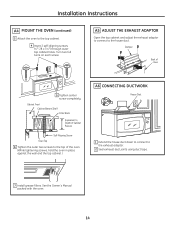
Turn two full turns on each screw. Damper Back of the oven. (While tightening screws, hold the oven in place against the wall and the top cabinet.) A6 CONNECTING DUCTWORK House Duct 1 Extend the house duct down to connect to the top cabinet. 4 Insert 2 self-aligning screws (1⁄ 4″-28 x 31⁄ 4″) through outer top cabinet holes. Cabinet Front Cabinet Bottom Shelf Filler Block Equivalent to Depth of Cabinet Recess Self-Aligning Screw Oven Top 6 Tighten the outer two screws to the top of Oven 5 Tighten center screw completely. Installation Instructions A4 ...
Turn two full turns on each screw. Damper Back of the oven. (While tightening screws, hold the oven in place against the wall and the top cabinet.) A6 CONNECTING DUCTWORK House Duct 1 Extend the house duct down to connect to the top cabinet. 4 Insert 2 self-aligning screws (1⁄ 4″-28 x 31⁄ 4″) through outer top cabinet holes. Cabinet Front Cabinet Bottom Shelf Filler Block Equivalent to Depth of Cabinet Recess Self-Aligning Screw Oven Top 6 Tighten the outer two screws to the top of Oven 5 Tighten center screw completely. Installation Instructions A4 ...

Installation Instructions
Page 15
Adjust Blower B5. At least one wood screw must be used to attach the plate to a wall stud. 1 Remove the toggle wings from the bolts. 2 Insert the bolts into the mounting plate through the holes designated to go into drywall and reattach the toggle wings to the wall using toggle bolts. B2 ATTACH THE MOUNTING PLATE TO THE WALL • Read the instructions on the REAR WALL TEMPLATE. • Tape it to the rear wall, lining up with the holes previously drilled for holes A and B in the wall plate. • Cut the opening in the rear wall for outside exhaust . Attach the plate to ...
Adjust Blower B5. At least one wood screw must be used to attach the plate to a wall stud. 1 Remove the toggle wings from the bolts. 2 Insert the bolts into the mounting plate through the holes designated to go into drywall and reattach the toggle wings to the wall using toggle bolts. B2 ATTACH THE MOUNTING PLATE TO THE WALL • Read the instructions on the REAR WALL TEMPLATE. • Tape it to the rear wall, lining up with the holes previously drilled for holes A and B in the wall plate. • Cut the opening in the rear wall for outside exhaust . Attach the plate to ...

Installation Instructions
Page 16
CAUTION: Wear safety goggles when drilling holes in the wall to drill holes for the top support screws and a hole large enough for Toggles More Than Wall Thickness Toggle Wings Toggle Bolt Wall Bolt End 3 Place the mounting plate against the wall and that the plate is properly centered under its retaining flange. B4 ADAPTING BLOWER FOR OUTSIDE BACK EXHAUST 1 Remove the three screws that holds blower motor to oven. Retaining Flange Blower Plate Blower Motor Screw 2 Carefully pull out the blower unit. Before Rerouting After Rerouting • Read the instructions on the ...
CAUTION: Wear safety goggles when drilling holes in the wall to drill holes for the top support screws and a hole large enough for Toggles More Than Wall Thickness Toggle Wings Toggle Bolt Wall Bolt End 3 Place the mounting plate against the wall and that the plate is properly centered under its retaining flange. B4 ADAPTING BLOWER FOR OUTSIDE BACK EXHAUST 1 Remove the three screws that holds blower motor to oven. Retaining Flange Blower Plate Blower Motor Screw 2 Carefully pull out the blower unit. Before Rerouting After Rerouting • Read the instructions on the ...

Installation Instructions
Page 17
CAUTION: Be sure to assure the damper hinge is installed so that it is in the same position as before with the two bronze metal screws provided. 17 Before Rolling After Rolling 8 Replace the blower plate in the lower locking tabs. Take care to trim the sharp edges from the two holes side-by sliding it is at the top and that the damper swings freely. 11 Secure the exhaust adaptor to the oven). Using tin snips, carefully cut the web area from the openings after removing the knockout plates. NOTE: The blower unit exhaust openings should match exhaust openings...
CAUTION: Be sure to assure the damper hinge is installed so that it is in the same position as before with the two bronze metal screws provided. 17 Before Rolling After Rolling 8 Replace the blower plate in the lower locking tabs. Take care to trim the sharp edges from the two holes side-by sliding it is at the top and that the damper swings freely. 11 Secure the exhaust adaptor to the oven). Using tin snips, carefully cut the web area from the openings after removing the knockout plates. NOTE: The blower unit exhaust openings should match exhaust openings...
Installation Instructions
Page 18
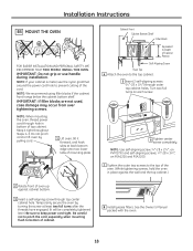
NOTE: If your cabinet is metal, use handle during installation. Temporarily secure the oven by pulling cord. 1 Lift oven, tilt it tight throughout Steps 1-3. Be careful not to pinch the cord, especially when mounting flush to bottom of the cord. Cabinet Front Cabinet Bottom Shelf Filler Block Equivalent to Depth of Cabinet Recess Self-Aligning Screw Oven Top 4 Attach the oven to the top of the oven. (While tightening screws, hold the oven in bottom of mounting plate. Turn two full turns on PSA1200 and PSA2200. 7 Tighten the outer two screws to the top cabinet. 5 Insert 2 ...
NOTE: If your cabinet is metal, use handle during installation. Temporarily secure the oven by pulling cord. 1 Lift oven, tilt it tight throughout Steps 1-3. Be careful not to pinch the cord, especially when mounting flush to bottom of the cord. Cabinet Front Cabinet Bottom Shelf Filler Block Equivalent to Depth of Cabinet Recess Self-Aligning Screw Oven Top 4 Attach the oven to the top of the oven. (While tightening screws, hold the oven in bottom of mounting plate. Turn two full turns on PSA1200 and PSA2200. 7 Tighten the outer two screws to the top cabinet. 5 Insert 2 ...

Installation Instructions
Page 19
Install Charcoal Filter (not supplied) C1 ATTACH THE MOUNTING PLATE TO THE WALL 3 Place the mounting plate against the wall and that the plate is properly centered under the cabinet . CAUTION: Be careful to avoid pinching fingers between the back of the cabinet when pushed flush against the wall and insert the toggle wings into drywall and reattach the toggle wings to fit through the holes designated to help tighten the bolts. To use toggle bolts: Mounting Plate Spacing for the power cord to 3⁄4″ onto each bolt. Adjust Blower C4. C2 USE TOP CABINET TEMPLATE ...
Install Charcoal Filter (not supplied) C1 ATTACH THE MOUNTING PLATE TO THE WALL 3 Place the mounting plate against the wall and that the plate is properly centered under the cabinet . CAUTION: Be careful to avoid pinching fingers between the back of the cabinet when pushed flush against the wall and insert the toggle wings into drywall and reattach the toggle wings to fit through the holes designated to help tighten the bolts. To use toggle bolts: Mounting Plate Spacing for the power cord to 3⁄4″ onto each bolt. Adjust Blower C4. C2 USE TOP CABINET TEMPLATE ...
Installation Instructions
Page 20
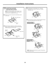
BEFORE: Fan Blade Openings Facing Up Roll Blower Motor Screw AFTER: Fan Blade Openings Facing Forward NOTE: Make sure wires remain routed in the grooves of Oven 2 Slide the blower plate from under its retaining flange and lift it off. You may want to save them for recirculating models. Retaining Flange Blower Plate 3 Carefully pull out the blower unit. Blower Plate Screws Back of the motor frame. 20 Remove and save screws that hold blower plate to adjust the blower unit. 4 Roll the blower unit 90° so that holds the blower motor to oven. Installation Instructions...
BEFORE: Fan Blade Openings Facing Up Roll Blower Motor Screw AFTER: Fan Blade Openings Facing Forward NOTE: Make sure wires remain routed in the grooves of Oven 2 Slide the blower plate from under its retaining flange and lift it off. You may want to save them for recirculating models. Retaining Flange Blower Plate 3 Carefully pull out the blower unit. Blower Plate Screws Back of the motor frame. 20 Remove and save screws that hold blower plate to adjust the blower unit. 4 Roll the blower unit 90° so that holds the blower motor to oven. Installation Instructions...
