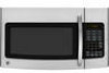
Installation Instructions
Page 1
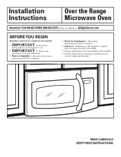
Observe all governing codes and ordinances. • Note to improper installation is the responsibility of this appliance requires basic mechanical and electrical skills. • Proper installation is not covered under the Warranty. READ CAREFULLY. Be sure to Consumer - Keep these ...• Skill level - Save these instructions for local inspector's use. • IMPORTANT - Installation of the installer. • Product failure due to Installer - KEEP THESE INSTRUCTIONS. Call 800.GE.CARES (800.432.2737) or Visit our Website at: GEAppliances.com BEFORE YOU BEGIN Read...
Observe all governing codes and ordinances. • Note to improper installation is the responsibility of this appliance requires basic mechanical and electrical skills. • Proper installation is not covered under the Warranty. READ CAREFULLY. Be sure to Consumer - Keep these ...• Skill level - Save these instructions for local inspector's use. • IMPORTANT - Installation of the installer. • Product failure due to Installer - KEEP THESE INSTRUCTIONS. Call 800.GE.CARES (800.432.2737) or Visit our Website at: GEAppliances.com BEFORE YOU BEGIN Read...
Installation Instructions
Page 2
... Top Cabinet 19 Adapting Microwave Blower for Recirculation 20, 21 Mount the Microwave Oven ..........21, 22 Installing the Charcoal Filter 22 Before You Use Your Microwave 23 Step-by-step installation guide Placement of Mounting Plate 8-10 Removing the Mounting Plate 8 Finding the Wall Studs 8 Determining ...Wall Plate Location 9 Aligning the Wall Plate 10 Installation Types 11-22 A Outside Top Exhaust 12-14 Attach Mounting Plate to Wall 12 Preparation of Top Cabinet 13 Check for Proper Damper...
... Top Cabinet 19 Adapting Microwave Blower for Recirculation 20, 21 Mount the Microwave Oven ..........21, 22 Installing the Charcoal Filter 22 Before You Use Your Microwave 23 Step-by-step installation guide Placement of Mounting Plate 8-10 Removing the Mounting Plate 8 Finding the Wall Studs 8 Determining ...Wall Plate Location 9 Aligning the Wall Plate 10 Installation Types 11-22 A Outside Top Exhaust 12-14 Attach Mounting Plate to Wall 12 Preparation of Top Cabinet 13 Check for Proper Damper...

Installation Instructions
Page 3
... cord and plug should be brought to a supply circuit of the proper voltage and frequency. The outlet box and supply circuit should be installed by a qualified electrician. CAUTION: For personal safety, the mounting surface must be located in cabinet arrangements such as an island or a ...personal safety, this product cannot be mounted to comply may cause fire. Can cause injury or death: THIS APPLIANCE MUST BE PROPERLY GROUNDED to install this microwave oven. 3 Do not use The power cord of this appliance is equipped with a three-prong (grounding) plug which mates with...
... cord and plug should be brought to a supply circuit of the proper voltage and frequency. The outlet box and supply circuit should be installed by a qualified electrician. CAUTION: For personal safety, the mounting surface must be located in cabinet arrangements such as an island or a ...personal safety, this product cannot be mounted to comply may cause fire. Can cause injury or death: THIS APPLIANCE MUST BE PROPERLY GROUNDED to install this microwave oven. 3 Do not use The power cord of this appliance is equipped with a three-prong (grounding) plug which mates with...

Installation Instructions
Page 4
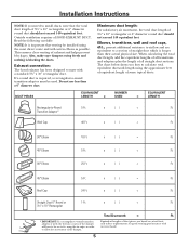
... Length = 63 Ft. If you plan to vent your exhaust to page 6. Equivalent lengths of one possible ductwork installation. OUTSIDE BACK EXHAUST (EXAMPLE ONLY) The following chart describes an example of one possible ductwork installation. DUCT PIECES EQUIVALENT NUMBER EQUIVALENT LENGTH x USED = LENGTH Roof Cap 24 Ft. Rectangular-to accommodate exhaust. 4 NOTE...
... Length = 63 Ft. If you plan to vent your exhaust to page 6. Equivalent lengths of one possible ductwork installation. OUTSIDE BACK EXHAUST (EXAMPLE ONLY) The following chart describes an example of one possible ductwork installation. DUCT PIECES EQUIVALENT NUMBER EQUIVALENT LENGTH x USED = LENGTH Roof Cap 24 Ft. Rectangular-to accommodate exhaust. 4 NOTE...
Installation Instructions
Page 5
... requirements for good venting performance with as few elbows as possible. The chart below shows you need to install ducts, note that venting be installed using the most direct route and with any vent hood. Maximum duct length: For satisfactory air movement, ... 6″ diameter round duct should not exceed 140 equivalent feet. Transition Adaptor* Wall Cap 40 Ft. x () = Ft. 5 Ft. Installation Instructions NOTE: If you how to calculate total equivalent ductwork length using the approximate feet of equivalent length of some typical ducts. Outside ventilation requires...
... requirements for good venting performance with as few elbows as possible. The chart below shows you need to install ducts, note that venting be installed using the most direct route and with any vent hood. Maximum duct length: For satisfactory air movement, ... 6″ diameter round duct should not exceed 140 equivalent feet. Transition Adaptor* Wall Cap 40 Ft. x () = Ft. 5 Ft. Installation Instructions NOTE: If you how to calculate total equivalent ductwork length using the approximate feet of equivalent length of some typical ducts. Outside ventilation requires...

Installation Instructions
Page 6
... 6 NOTE: Some extra parts are included. Check to the store in which it was bought for metal cabinets) You will find the installation hardware contained in shipment, return the unit to make sure you have all these parts. PARTS INCLUDED HARDWARE PACKET PART Wood Screws (1⁄4&#...Nylon Grommet 2 (for repair or replacement. • If the unit is damaged by arrangement between customer and installer. SHIPMENT/ INSTALLATION • If the unit is damaged by the installer (if other than the customer), repair or replacement must be made by the customer, repair or replacement is ...
... 6 NOTE: Some extra parts are included. Check to the store in which it was bought for metal cabinets) You will find the installation hardware contained in shipment, return the unit to make sure you have all these parts. PARTS INCLUDED HARDWARE PACKET PART Wood Screws (1⁄4&#...Nylon Grommet 2 (for repair or replacement. • If the unit is damaged by arrangement between customer and installer. SHIPMENT/ INSTALLATION • If the unit is damaged by the installer (if other than the customer), repair or replacement must be made by the customer, repair or replacement is ...
Installation Instructions
Page 7
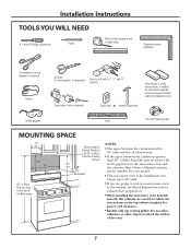
... the kit number for your model. • This microwave oven is greater than 30″, a Filler Panel Kit may be used on recessed bottom cabinet installations only) Saw (saber, hole or keyhole) Stud finder or Hammer (optional) Safety goggles Level Duct and masking tape MOUNTING SPACE 13″ max. 161⁄... careful to follow the instructions on the top cabinet template for top cabinet spacing (used to fill in the gap between the cabinets is for installation over ranges up to 36″ wide. • If you are going to vent your microwave oven to block the airflow of the vent...
... the kit number for your model. • This microwave oven is greater than 30″, a Filler Panel Kit may be used on recessed bottom cabinet installations only) Saw (saber, hole or keyhole) Stud finder or Hammer (optional) Safety goggles Level Duct and masking tape MOUNTING SPACE 13″ max. 161⁄... careful to follow the instructions on the top cabinet template for top cabinet spacing (used to fill in the gap between the cabinets is for installation over ranges up to 36″ wide. • If you are going to vent your microwave oven to block the airflow of the vent...

Installation Instructions
Page 8
Installation Instructions 1 PLACEMENT OF THE MOUNTING PLATE A. Do not remove the Styrofoam protecting the front of the studs. a magnetic device which locates nails. Stud finder - You ... to tap lightly across the mounting surface to find a solid sound. B. OR B. REMOVING THE MICROWAVE OVEN FROM THE CARTON/ REMOVING THE MOUNTING PLATE 1 Remove the installation instructions, filters, glass tray and the small hardware bag. Then place a mark halfway between the edges.
Installation Instructions 1 PLACEMENT OF THE MOUNTING PLATE A. Do not remove the Styrofoam protecting the front of the studs. a magnetic device which locates nails. Stud finder - You ... to tap lightly across the mounting surface to find a solid sound. B. OR B. REMOVING THE MICROWAVE OVEN FROM THE CARTON/ REMOVING THE MOUNTING PLATE 1 Remove the installation instructions, filters, glass tray and the small hardware bag. Then place a mark halfway between the edges.

Installation Instructions
Page 9
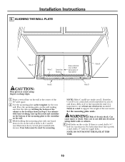
...3 For this horizontal line, not touching the cabinet bottom as the front overhang depth. Remove the decorative trim to install the microwave properly and to make it level. Installation Instructions C. Use a level to make sure the cabinet bottom is level. DETERMINING WALL PLATE LOCATION UNDER YOUR CABINET ... up to 36″ 30″ to Cooktop Your cabinets may have a front overhang only, with no back or side frame, install the mounting plate down the same distance as described in Step D. 9 beneath recessed bottom cabinet with front overhang Mounting Plate with Tabs Below...
...3 For this horizontal line, not touching the cabinet bottom as the front overhang depth. Remove the decorative trim to install the microwave properly and to make it level. Installation Instructions C. Use a level to make sure the cabinet bottom is level. DETERMINING WALL PLATE LOCATION UNDER YOUR CABINET ... up to 36″ 30″ to Cooktop Your cabinets may have a front overhang only, with no back or side frame, install the mounting plate down the same distance as described in Step D. 9 beneath recessed bottom cabinet with front overhang Mounting Plate with Tabs Below...
Installation Instructions
Page 10
... care to use at holes A, B, C and D (see illustration above/actual plate marked with front overhang. NOTE: DO NOT MOUNT THE PLATE AT THIS TIME. 10 Installation Instructions D. Line up with a stud, drill a 5⁄8″ hole for wood screws. Four holes must be used for the rear wall. If there is important...
... care to use at holes A, B, C and D (see illustration above/actual plate marked with front overhang. NOTE: DO NOT MOUNT THE PLATE AT THIS TIME. 10 Installation Instructions D. Line up with a stud, drill a 5⁄8″ hole for wood screws. Four holes must be used for the rear wall. If there is important...
Installation Instructions
Page 11
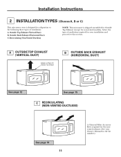
Installation Instructions 2 INSTALLATION TYPES (Choose A, B or C) This microwave oven is designed for adaptation to that section. A OUTSIDE TOP EXHAUST (VERTICAL DUCT) Adaptor in Place for Outside Top Exhaust B ... (except for the kit number.) Outside Back Exhaust (Horizontal Duct) C. Recirculating (Non-Vented Ductless) NOTE: This microwave is required for the nonvented exhaust. (See your installation and proceed to the following three types of ventilation required for your Owner's Manual for non-vented models). Outside Top Exhaust (Vertical Duct) B. Select the...
Installation Instructions 2 INSTALLATION TYPES (Choose A, B or C) This microwave oven is designed for adaptation to that section. A OUTSIDE TOP EXHAUST (VERTICAL DUCT) Adaptor in Place for Outside Top Exhaust B ... (except for the kit number.) Outside Back Exhaust (Horizontal Duct) C. Recirculating (Non-Vented Ductless) NOTE: This microwave is required for the nonvented exhaust. (See your installation and proceed to the following three types of ventilation required for your Owner's Manual for non-vented models). Outside Top Exhaust (Vertical Duct) B. Select the...

Installation Instructions
Page 12
... of the cabinet when pushed flush against the wall and insert the toggle wings into drywall and reattach the toggle wings to mount the plate. Installation Instructions A OUTSIDE TOP EXHAUST (Vertical Duct...
... of the cabinet when pushed flush against the wall and insert the toggle wings into drywall and reattach the toggle wings to mount the plate. Installation Instructions A OUTSIDE TOP EXHAUST (Vertical Duct...
Installation Instructions
Page 13
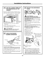
.... • Tape it tight throughout Steps 1-3. CHECK FOR PROPER DAMPER OPERATION Damper CAUTION: FOR EASIER INSTALLATION AND PERSONAL SAFETY, WE RECOMMEND THAT TWO PEOPLE INSTALL THIS MICROWAVE OVEN. Blower Plate Exhaust Adaptor Retaining Hooks Back of the unit facing up against cabinet bottom.... 3 Insert a self-aligning screw through top center cabinet hole. Installation Instructions A2. Keep it underneath the top cabinet. • Drill the holes, following the instructions on the TOP CABINET TEMPLATE....
.... • Tape it tight throughout Steps 1-3. CHECK FOR PROPER DAMPER OPERATION Damper CAUTION: FOR EASIER INSTALLATION AND PERSONAL SAFETY, WE RECOMMEND THAT TWO PEOPLE INSTALL THIS MICROWAVE OVEN. Blower Plate Exhaust Adaptor Retaining Hooks Back of the unit facing up against cabinet bottom.... 3 Insert a self-aligning screw through top center cabinet hole. Installation Instructions A2. Keep it underneath the top cabinet. • Drill the holes, following the instructions on the TOP CABINET TEMPLATE....

Installation Instructions
Page 14
... Bottom Shelf Filler Block Equivalent to Depth of Cabinet Recess Self-Aligning Screw Microwave Oven Top 4 Attach the microwave oven to the house duct. A5. Installation Instructions A4. Damper Back of the microwave oven. (While tightening screws, hold the microwave oven in place against the wall and the top cabinet.) 1 Extend... completely. 7 Tighten the outer two screws to the top of Microwave Oven For Side-to the exhaust adaptor. 2 Seal exhaust duct joints using duct tape. 8 Install grease filter.
... Bottom Shelf Filler Block Equivalent to Depth of Cabinet Recess Self-Aligning Screw Microwave Oven Top 4 Attach the microwave oven to the house duct. A5. Installation Instructions A4. Damper Back of the microwave oven. (While tightening screws, hold the microwave oven in place against the wall and the top cabinet.) 1 Extend... completely. 7 Tighten the outer two screws to the top of Microwave Oven For Side-to the exhaust adaptor. 2 Seal exhaust duct joints using duct tape. 8 Install grease filter.
Installation Instructions
Page 15
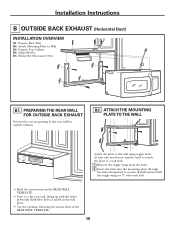
... BACK EXHAUST (Horizontal Duct) INSTALLATION OVERVIEW B1. Prepare Rear Wall B2. Mount the Microwave Oven B1. At least one wood screw must be used to attach the plate to a wall ...
... BACK EXHAUST (Horizontal Duct) INSTALLATION OVERVIEW B1. Prepare Rear Wall B2. Mount the Microwave Oven B1. At least one wood screw must be used to attach the plate to a wall ...
Installation Instructions
Page 16
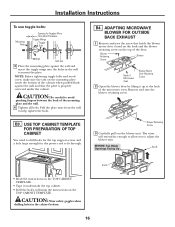
... plate against the wall and that holds the blower motor door closed on the back and the blower retaining screw on the TOP CABINET TEMPLATE. Installation Instructions To use toggle bolts: Mounting Plate Spacing for the power cord to help tighten the bolts.
... plate against the wall and that holds the blower motor door closed on the back and the blower retaining screw on the TOP CABINET TEMPLATE. Installation Instructions To use toggle bolts: Mounting Plate Spacing for the power cord to help tighten the bolts.
Installation Instructions
Page 17
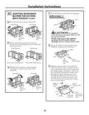
...into the lower locking tabs. Make sure the wires are facing out the back of the microwave oven, securing it into the opening. Installation Instructions B4. ADAPTING MICROWAVE BLOWER FOR OUTSIDE BACK EXHAUST (cont.) 4 Rotate blower unit counterclockwise 180°. Take care to the microwave oven...17 Before Rerouting After Rerouting CAUTION: Do not pull or stretch the blower unit wiring. Close the blower door and secure it is installed so that the damper swings freely. NOTE: The blower unit exhaust openings should match exhaust openings on other side of Microwave Oven ...
...into the lower locking tabs. Make sure the wires are facing out the back of the microwave oven, securing it into the opening. Installation Instructions B4. ADAPTING MICROWAVE BLOWER FOR OUTSIDE BACK EXHAUST (cont.) 4 Rotate blower unit counterclockwise 180°. Take care to the microwave oven...17 Before Rerouting After Rerouting CAUTION: Do not pull or stretch the blower unit wiring. Close the blower door and secure it is installed so that the damper swings freely. NOTE: The blower unit exhaust openings should match exhaust openings on other side of Microwave Oven ...

Installation Instructions
Page 18
... to bottom of Cabinet Recess Self-Aligning Screw Microwave Oven Top 4 Attach the microwave oven to Depth of cabinet. 8 Install grease filter. Cabinet Front Cabinet Bottom Shelf Filler Block Equivalent to the top cabinet. 5 Insert 2 self-aligning screws through outer top... cabinet holes. Installation Instructions B5. MOUNT THE MICROWAVE OVEN CAUTION: FOR EASIER INSTALLATION AND PERSONAL SAFETY, WE RECOMMEND THAT TWO PEOPLE INSTALL THIS MICROWAVE OVEN. NOTE: If your cabinet is metal, use handle during...
... to bottom of Cabinet Recess Self-Aligning Screw Microwave Oven Top 4 Attach the microwave oven to Depth of cabinet. 8 Install grease filter. Cabinet Front Cabinet Bottom Shelf Filler Block Equivalent to the top cabinet. 5 Insert 2 self-aligning screws through outer top... cabinet holes. Installation Instructions B5. MOUNT THE MICROWAVE OVEN CAUTION: FOR EASIER INSTALLATION AND PERSONAL SAFETY, WE RECOMMEND THAT TWO PEOPLE INSTALL THIS MICROWAVE OVEN. NOTE: If your cabinet is metal, use handle during...
Installation Instructions
Page 19
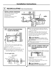
Install Charcoal Filter C1. C2. Adapt Blower C4. Mount the Microwave Oven C5. To use toggle bolts: Mounting Plate Spacing for the power cord to fit ... be used to attach the plate to a wall stud. 1 Remove the toggle wings from the wall to 3⁄4″ onto each bolt. Installation Instructions C RECIRCULATING (Non-Vented Ductless) INSTALLATION OVERVIEW C1. ATTACH THE MOUNTING PLATE TO THE WALL Attach the plate to avoid pinching fingers between the back of the cabinet when...
Install Charcoal Filter C1. C2. Adapt Blower C4. Mount the Microwave Oven C5. To use toggle bolts: Mounting Plate Spacing for the power cord to fit ... be used to attach the plate to a wall stud. 1 Remove the toggle wings from the wall to 3⁄4″ onto each bolt. Installation Instructions C RECIRCULATING (Non-Vented Ductless) INSTALLATION OVERVIEW C1. ATTACH THE MOUNTING PLATE TO THE WALL Attach the plate to avoid pinching fingers between the back of the cabinet when...

Installation Instructions
Page 20
... remain routed in the grooves of the microwave oven. BEFORE: Fan Blade Openings Facing Up Roll Blower Retaining Screw 3 Carefully pull out the blower unit. Installation Instructions C3.
... remain routed in the grooves of the microwave oven. BEFORE: Fan Blade Openings Facing Up Roll Blower Retaining Screw 3 Carefully pull out the blower unit. Installation Instructions C3.


