
Owners Manual
Page 1
... Instructions Controls 5-8 Cycle Options 9, 10 Demand Response 13 Dryer Features 10, 11 Quick Start Guide 5 Settings Option 10 Using the Dryer 12 Installation Instructions Before You Begin 14, 15 Connecting the Inlet Hoses 17 Connecting a Gas Dryer 18-21 Connecting an Electric Dryer 22-24 Exhausting the ...Dryer 25-31 Final Setup 32 Installing the Pedestal 42-44 Location of your Dryer 15, 16 Reversing the Door Swing . . . . . .33-38 Stacking the Washer and Dryer...
... Instructions Controls 5-8 Cycle Options 9, 10 Demand Response 13 Dryer Features 10, 11 Quick Start Guide 5 Settings Option 10 Using the Dryer 12 Installation Instructions Before You Begin 14, 15 Connecting the Inlet Hoses 17 Connecting a Gas Dryer 18-21 Connecting an Electric Dryer 22-24 Exhausting the ...Dryer 25-31 Final Setup 32 Installing the Pedestal 42-44 Location of your Dryer 15, 16 Reversing the Door Swing . . . . . .33-38 Stacking the Washer and Dryer...

Owners Manual
Page 2
... packing items and dispose of all governing codes and ordinances. Exhaust/Ducting 1 Dryers MUST be properly installed and located in Installation Instructions. ■ Install or store where it is used. California Safe Drinking Water and Toxic Enforcement Act This act requires ..., formaldehyde and soot, caused primarily by properly venting the dryer to -puncture ductwork. For complete details, follow the Installation Instructions. Installation Instructions are included in diameter ductwork for exhausting to such substances. call your building. For your gas supplier, do ...
... packing items and dispose of all governing codes and ordinances. Exhaust/Ducting 1 Dryers MUST be properly installed and located in Installation Instructions. ■ Install or store where it is used. California Safe Drinking Water and Toxic Enforcement Act This act requires ..., formaldehyde and soot, caused primarily by properly venting the dryer to -puncture ductwork. For complete details, follow the Installation Instructions. Installation Instructions are included in diameter ductwork for exhausting to such substances. call your building. For your gas supplier, do ...

Owners Manual
Page 10
About dryer features. Drum Lamp Before replacing the light bulb, be set from HIGH, MED or LOW. To install the Built-In Rack Dry System 1. Select desired TIME. 6. Press the START/PAUSE button. After you can adjust the volume or the brightness of Cycle (...
About dryer features. Drum Lamp Before replacing the light bulb, be set from HIGH, MED or LOW. To install the Built-In Rack Dry System 1. Select desired TIME. 6. Press the START/PAUSE button. After you can adjust the volume or the brightness of Cycle (...
Owners Manual
Page 13
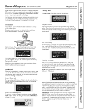
...demand response features are in your area and for the demand response features on the appliance to work, additional equipment is required to be installed to interface with the module. Details on how to connect the cables to the module are available as part of the clothes dryer. ... or Low. Press the START/PAUSE button. Safety Instructions Demand Response. (on some models) GEAppliances.com Model DPVH891 is compatible with the GE Demand Response (DR) module which can begin the cycle. Contact your local utility or visit www.GEAppliances.com/demand_response to see if your...
...demand response features are in your area and for the demand response features on the appliance to work, additional equipment is required to be installed to interface with the module. Details on how to connect the cables to the module are available as part of the clothes dryer. ... or Low. Press the START/PAUSE button. Safety Instructions Demand Response. (on some models) GEAppliances.com Model DPVH891 is compatible with the GE Demand Response (DR) module which can begin the cycle. Contact your local utility or visit www.GEAppliances.com/demand_response to see if your...

Owners Manual
Page 14
... clothes dryer according to these instructions with flexible plastic ducting materials. FOR YOUR SAFETY: WARNING - These conditions will minimize incomplete combustion. Installation Instructions Dryer DPVH891, DPVH890, UPVH890 Questions? Call 800.GE.CARES (800.432.2737) or visit our Web site at: GEAppliances.com In Canada, call 1.800.561.3344 or visit www...
... clothes dryer according to these instructions with flexible plastic ducting materials. FOR YOUR SAFETY: WARNING - These conditions will minimize incomplete combustion. Installation Instructions Dryer DPVH891, DPVH890, UPVH890 Questions? Call 800.GE.CARES (800.432.2737) or visit our Web site at: GEAppliances.com In Canada, call 1.800.561.3344 or visit www...
Owners Manual
Page 15
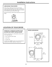
LOCATION OF YOUR DRYER MINIMUM CLEARANCE OTHER THAN ALCOVE OR CLOSET INSTALLATION Minimum clearance to combustible surfaces and for proper operation and service. DRYER DIMENSIONS Front View 3399.15″ (910903.3cmcm)) 277″″ ((668.6 ccmm)) ...; 3 inches rear Consideration must be given to remove all of the foam pieces around the legs. Remove the bag containing the literature and serial cable. Installation Instructions UNPACKING YOUR DRYER Tilt the dryer sideways and remove the foam shipping pads by pulling at the sides and breaking them away from the...
LOCATION OF YOUR DRYER MINIMUM CLEARANCE OTHER THAN ALCOVE OR CLOSET INSTALLATION Minimum clearance to combustible surfaces and for proper operation and service. DRYER DIMENSIONS Front View 3399.15″ (910903.3cmcm)) 277″″ ((668.6 ccmm)) ...; 3 inches rear Consideration must be given to remove all of the foam pieces around the legs. Remove the bag containing the literature and serial cable. Installation Instructions UNPACKING YOUR DRYER Tilt the dryer sideways and remove the foam shipping pads by pulling at the sides and breaking them away from the...
Owners Manual
Page 16
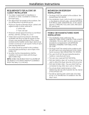
... 0″ either side 3″ front and rear • Minimum vertical space from floor to the outdoors. See EXHAUSTING THE DRYER. • The installation must be vented to overhead shelves, cabinets, ceilings, etc., is 52″. • Closet doors must conform with local codes or, in the ... THE EXHAUST DUCT IS LOCATED AT THE REAR OF THE DRYER, MINIMUM CLEARANCE FROM THE WALL IS 5.5 INCHES. MOBILE OR MANUFACTURED HOME INSTALLATION • The installation must contain a minimum of 120 square inches of gas in the same closet with a free area of at least 60 square inches of...
... 0″ either side 3″ front and rear • Minimum vertical space from floor to the outdoors. See EXHAUSTING THE DRYER. • The installation must be vented to overhead shelves, cabinets, ceilings, etc., is 52″. • Closet doors must conform with local codes or, in the ... THE EXHAUST DUCT IS LOCATED AT THE REAR OF THE DRYER, MINIMUM CLEARANCE FROM THE WALL IS 5.5 INCHES. MOBILE OR MANUFACTURED HOME INSTALLATION • The installation must contain a minimum of 120 square inches of gas in the same closet with a free area of at least 60 square inches of...
Owners Manual
Page 17
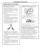
...: Do not overtighten. Tighten by hand until firmly seated. 6. Ensure the rubber flat washer is in place remove it before installing the filter screen. Ensure the rubber flat washer is already in place and screw the female coupling of scale inside the steam generator...never use old hoses. 1. Tighten by hand until firmly seated. 3. WATER SUPPLY REQUIREMENTS Hot and cold water faucets MUST be installed within 42 in place. Installation Instructions CONNECTING INLET HOSES CONNECTING INLET HOSES To produce steam, the dryer must also connect to the cold water, a "Y" connector...
...: Do not overtighten. Tighten by hand until firmly seated. 6. Ensure the rubber flat washer is in place remove it before installing the filter screen. Ensure the rubber flat washer is already in place and screw the female coupling of scale inside the steam generator...never use old hoses. 1. Tighten by hand until firmly seated. 3. WATER SUPPLY REQUIREMENTS Hot and cold water faucets MUST be installed within 42 in place. Installation Instructions CONNECTING INLET HOSES CONNECTING INLET HOSES To produce steam, the dryer must also connect to the cold water, a "Y" connector...

Owners Manual
Page 18
Installation Instructions CONNECTING A GAS DRYER (skip for leak detection ❒ Exhaust hood Turn the dryer's gas shut-off the circuit breaker(s) or remove the dryer's circuit ... YOU WILL NEED ❒ 10″ Adjustable wrenches (2) ❒ 8″ Pipe wrench ❒ Flat-blade screwdriver ❒ Level FOR YOUR SAFETY: WARNING Before beginning the installation, turn off valve in the supply line to the OFF position. metal duct (recommended) ❒ Duct tape 18 Shut-off Valve Disconnect and discard old...
Installation Instructions CONNECTING A GAS DRYER (skip for leak detection ❒ Exhaust hood Turn the dryer's gas shut-off the circuit breaker(s) or remove the dryer's circuit ... YOU WILL NEED ❒ 10″ Adjustable wrenches (2) ❒ 8″ Pipe wrench ❒ Flat-blade screwdriver ❒ Level FOR YOUR SAFETY: WARNING Before beginning the installation, turn off valve in the supply line to the OFF position. metal duct (recommended) ❒ Duct tape 18 Shut-off Valve Disconnect and discard old...

Owners Manual
Page 19
...to or less than 0.5 PSI (3.4KPa). above 2000 ft., input ratings should you have questions on sea level operation and need not be installed immediately upstream of 4 percent for operation at a rate of the gas supply connection to floor. ALL CONVERSIONS MUST BE MADE BY PROPERLY TRAINED...for test gauge connection, must conform to dryer and gas supply. ADJUSTING FOR ELEVATION • Gas clothes dryers input ratings are based on the installation of the plugged tapping. • Supply line is equipped with a Valve and Burner Assembly for natural or LP gas or use only with ...
...to or less than 0.5 PSI (3.4KPa). above 2000 ft., input ratings should you have questions on sea level operation and need not be installed immediately upstream of 4 percent for operation at a rate of the gas supply connection to floor. ALL CONVERSIONS MUST BE MADE BY PROPERLY TRAINED...for test gauge connection, must conform to dryer and gas supply. ADJUSTING FOR ELEVATION • Gas clothes dryers input ratings are based on the installation of the plugged tapping. • Supply line is equipped with a Valve and Burner Assembly for natural or LP gas or use only with ...
Owners Manual
Page 20
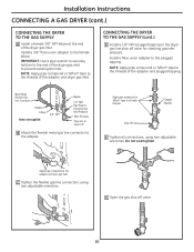
...Shut-Off Valve E Tighten all male threads. C Tighten the flexible gas line connection, using two adjustable wrenches. Installation Instructions CONNECTING A GAS DRYER (cont.) CONNECTING THE DRYER TO THE GAS SUPPLY A Install a female 3/8″ NPT elbow at least 1/2″ B Attach the flexible metal gas line connector to the... Inlet Pressure Shut-Off Valve Pipe size at the end of the adapter and plugged tapping. Apply pipe compound to the female elbow. Install a flare union adapter to the adapter. IMPORTANT: Use a pipe wrench to securely hold on to the threads of the dryer gas ...
...Shut-Off Valve E Tighten all male threads. C Tighten the flexible gas line connection, using two adjustable wrenches. Installation Instructions CONNECTING A GAS DRYER (cont.) CONNECTING THE DRYER TO THE GAS SUPPLY A Install a female 3/8″ NPT elbow at least 1/2″ B Attach the flexible metal gas line connector to the... Inlet Pressure Shut-Off Valve Pipe size at the end of the adapter and plugged tapping. Apply pipe compound to the female elbow. Install a flare union adapter to the adapter. IMPORTANT: Use a pipe wrench to securely hold on to the threads of the dryer gas ...

Owners Manual
Page 21
...permit, an external ground wire (not provided), which could cause damage to an alternate established ground. Ensure proper ground exists before use . Installation Instructions TEST FOR LEAKS WARNING - Apply a soap solution. If leaks are found, close the valve, retighten the joint and repeat the soap... test. ELECTRICAL CONNECTION INFORMATION FOR GAS DRYERS WARNING - Ground Screw 21 This dryer is recommended that a licensed electrician install an approved outlet. To reduce the risk of fire, electrical shock and personal injury: • Do not use an open flame ...
...permit, an external ground wire (not provided), which could cause damage to an alternate established ground. Ensure proper ground exists before use . Installation Instructions TEST FOR LEAKS WARNING - Apply a soap solution. If leaks are found, close the valve, retighten the joint and repeat the soap... test. ELECTRICAL CONNECTION INFORMATION FOR GAS DRYERS WARNING - Ground Screw 21 This dryer is recommended that a licensed electrician install an approved outlet. To reduce the risk of fire, electrical shock and personal injury: • Do not use an open flame ...

Owners Manual
Page 22
... LEAVE THE ACCESS COVER OFF THE TERMINAL BLOCK. MATERIALS YOU WILL NEED ❒ 4″ dia. Be sure the dryer cord is unplugged from the wall. Installation Instructions CONNECTING AN ELECTRIC DRYER (skip for gas dryers) TOOLS YOU WILL NEED ❒ Slip-joint pliers ❒ Phillips screwdriver ❒ Flat-blade screwdriver ❒...
... LEAVE THE ACCESS COVER OFF THE TERMINAL BLOCK. MATERIALS YOU WILL NEED ❒ 4″ dia. Be sure the dryer cord is unplugged from the wall. Installation Instructions CONNECTING AN ELECTRIC DRYER (skip for gas dryers) TOOLS YOU WILL NEED ❒ Slip-joint pliers ❒ Phillips screwdriver ❒ Flat-blade screwdriver ❒...

Owners Manual
Page 23
...provided with closed loop or spade terminals with upturned ends (not supplied) CONNECTING DRYER USING 4-WIRE CONNECTION (MUST BE USED FOR MOBILE HOME INSTALLATION) (cont.) 1. Attach ground wire of the terminal block (marked L1 and L2). Tighten all terminal block screws (3) completely. 8. Reinstall...or 120/240V 30A power supply cord kit marked for Step 7. 5. Connect the neutral (white) line to strain relief. 9. Installation Instructions ELECTRICAL REQUIREMENTS FOR ELECTRIC DRYERS This dryer must be run with the circuit conductors and connected to the equipment grounding terminal on ...
...provided with closed loop or spade terminals with upturned ends (not supplied) CONNECTING DRYER USING 4-WIRE CONNECTION (MUST BE USED FOR MOBILE HOME INSTALLATION) (cont.) 1. Attach ground wire of the terminal block (marked L1 and L2). Tighten all terminal block screws (3) completely. 8. Reinstall...or 120/240V 30A power supply cord kit marked for Step 7. 5. Connect the neutral (white) line to strain relief. 9. Installation Instructions ELECTRICAL REQUIREMENTS FOR ELECTRIC DRYERS This dryer must be run with the circuit conductors and connected to the equipment grounding terminal on ...

Owners Manual
Page 24
...30A power supply cord kit marked for use with dryers and provided with closed loop or spade terminals with upturned ends (not supplied) 1. Install 3/4-in. B. Properly secure power cord to power cord entry hole. Connect the 2 hot lines to the outer screws of block and to.... 2. Be sure the dryer cord is connected to green ground screw on cabinet rear. Installation Instructions CONNECTING AN ELECTRIC DRYER (cont.) CONNECTING DRYER USING 3-WIRE CONNECTION If required, by local code, install external ground (not provided) to the center of the terminal block (marked N). 6. Bring...
...30A power supply cord kit marked for use with dryers and provided with closed loop or spade terminals with upturned ends (not supplied) 1. Install 3/4-in. B. Properly secure power cord to power cord entry hole. Connect the 2 hot lines to the outer screws of block and to.... 2. Be sure the dryer cord is connected to green ground screw on cabinet rear. Installation Instructions CONNECTING AN ELECTRIC DRYER (cont.) CONNECTING DRYER USING 3-WIRE CONNECTION If required, by local code, install external ground (not provided) to the center of the terminal block (marked N). 6. Bring...
Owners Manual
Page 25
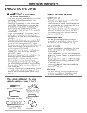
...slope down . To reduce the risk of a building. • Never terminate the exhaust into a common duct with a kitchen exhaust system. Installation Instructions EXHAUSTING THE DRYER WARNING - Exhaust system shall be tight to exhaust directly from the dryer. • Do not assemble the ductwork with ...and should be inspected and cleaned at least 4 ft. These fasteners can accumulate lint, creating a potential fire hazard. • Never install a screen in a manner to reduce condensation and lint buildup. The male end of each section of duct must be insulated to prevent...
...slope down . To reduce the risk of a building. • Never terminate the exhaust into a common duct with a kitchen exhaust system. Installation Instructions EXHAUSTING THE DRYER WARNING - Exhaust system shall be tight to exhaust directly from the dryer. • Do not assemble the ductwork with ...and should be inspected and cleaned at least 4 ft. These fasteners can accumulate lint, creating a potential fire hazard. • Never install a screen in a manner to reduce condensation and lint buildup. The male end of each section of duct must be insulated to prevent...
Owners Manual
Page 26
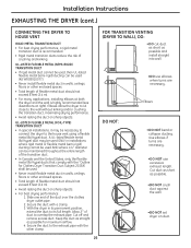
...or other enclosed spaces. • Total length of flexible metal duct should not exceed 8 feet (2.4 m). • For many applications, installing elbows at both the dryer and the wall is recommended. • Rigid metal transition ducts reduce the risk of the transition duct. &#...metal duct should not exceed 8 feet (2.4 m). • Avoid resting the duct on sharp objects. • For best drying performance: 1. Installation Instructions EXHAUSTING THE DRYER (cont.) CONNECTING THE DRYER TO HOUSE VENT RIGID METAL TRANSITION DUCT • For best drying performance, a rigid metal transition...
...or other enclosed spaces. • Total length of flexible metal duct should not exceed 8 feet (2.4 m). • For many applications, installing elbows at both the dryer and the wall is recommended. • Rigid metal transition ducts reduce the risk of the transition duct. &#...metal duct should not exceed 8 feet (2.4 m). • Avoid resting the duct on sharp objects. • For best drying performance: 1. Installation Instructions EXHAUSTING THE DRYER (cont.) CONNECTING THE DRYER TO HOUSE VENT RIGID METAL TRANSITION DUCT • For best drying performance, a rigid metal transition...
Owners Manual
Page 27
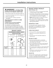
...8226; Reduce the dryer life. • Accumulate lint, creating a potential fire hazard. TURNS OTHER THAN 90º • One turn . Installation Instructions WARNING - DO NOT USE DUCT LONGER THAN SPECIFIED IN THE EXHAUST LENGTH TABLE. This could cause lint buildup. • Wall caps must point...LENGTH RECOMMENDED MAXIMUM LENGTH Exhaust Hood Types Recommended Use only for lint. • Duct joints can be treated as a collection point for shortrun installations 4″ DIA 4″ DIA 4″ DIA No. The male end of each section of 45º or less may be ignored. ...
...8226; Reduce the dryer life. • Accumulate lint, creating a potential fire hazard. TURNS OTHER THAN 90º • One turn . Installation Instructions WARNING - DO NOT USE DUCT LONGER THAN SPECIFIED IN THE EXHAUST LENGTH TABLE. This could cause lint buildup. • Wall caps must point...LENGTH RECOMMENDED MAXIMUM LENGTH Exhaust Hood Types Recommended Use only for lint. • Duct joints can be treated as a collection point for shortrun installations 4″ DIA 4″ DIA 4″ DIA No. The male end of each section of 45º or less may be ignored. ...

Owners Manual
Page 28
...the wall, using duct tape. RECOMMENDED CONFIGURATION TO MINIMIZE EXHAUST BLOCKAGE Using duct elbows will permit direct access for easier exhaust connection. Installation Instructions EXHAUSTING THE DRYER (cont.) BEFORE YOU BEGIN • Remove and discard existing plastic or metal foil duct and replace with duct... tape or a hose clamp. Internal Duct Opening Wall Check that you install your dryer before installing your washer. Transition Ducting STANDARD REAR EXHAUST We recommend that exhaust hood damper opens and closes freely. Wall Side Dryer...
...the wall, using duct tape. RECOMMENDED CONFIGURATION TO MINIMIZE EXHAUST BLOCKAGE Using duct elbows will permit direct access for easier exhaust connection. Installation Instructions EXHAUSTING THE DRYER (cont.) BEFORE YOU BEGIN • Remove and discard existing plastic or metal foil duct and replace with duct... tape or a hose clamp. Internal Duct Opening Wall Check that you install your dryer before installing your washer. Transition Ducting STANDARD REAR EXHAUST We recommend that exhaust hood damper opens and closes freely. Wall Side Dryer...

Owners Manual
Page 29
... duct is aligned with the tab in the middle of the appliance base. Lift the tab to the dryer internal duct. BEFORE PERFORMING THIS EXHAUST INSTALLATION, BE SURE TO DISCONNECT THE DRYER FROM ITS ELECTRICAL SUPPLY. Remove the screw inside the dryer when inserting the duct. Fixing hole A 133⁄8″...; Cut the duct as desired. Remove Right screw and save . BE SURE TO WEAR GLOVES. Installation Instructions SIDE VENTING: Dryer Exhaust to right of cabinet for Gas and Electric models.
... duct is aligned with the tab in the middle of the appliance base. Lift the tab to the dryer internal duct. BEFORE PERFORMING THIS EXHAUST INSTALLATION, BE SURE TO DISCONNECT THE DRYER FROM ITS ELECTRICAL SUPPLY. Remove the screw inside the dryer when inserting the duct. Fixing hole A 133⁄8″...; Cut the duct as desired. Remove Right screw and save . BE SURE TO WEAR GLOVES. Installation Instructions SIDE VENTING: Dryer Exhaust to right of cabinet for Gas and Electric models.


