
Installation Instructions
Page 1
...; If a new electrical outlet is required, its installation should be completed by a qualified electrician before the Microwave Oven is not covered under the Warranty. • Please read all instructions thoroughly before installing the Over the Range Microwave Oven. Two people are recommended to leave these instructions completely and carefully. • IMPORTANT - See 3 ELECTRICAL GROUNDING...
...; If a new electrical outlet is required, its installation should be completed by a qualified electrician before the Microwave Oven is not covered under the Warranty. • Please read all instructions thoroughly before installing the Over the Range Microwave Oven. Two people are recommended to leave these instructions completely and carefully. • IMPORTANT - See 3 ELECTRICAL GROUNDING...

Installation Instructions
Page 2
... use of the grounding plug can be attached to fill in the gaps. Ground Receptacle The unit should be installed before the Microwave Oven/Hood is 36 or 42 inches, a Filler Panel Kit can result in Figure 2. This will normally be stored in the top cabinet above the.... In the event of an electrical short circuit, grounding reduces risk of electric shock. 12" 30" 15.5" Backsplash At least 2" 30" or more from floor ELECTRICAL REQUIREMENTS The oven is needed for a 36-inch opening and 2 sets for ordering information. DO NOT UNDER ANY CIRCUMSTANCES CUT OR REMOVE THE GROUNDING...
... use of the grounding plug can be attached to fill in the gaps. Ground Receptacle The unit should be installed before the Microwave Oven/Hood is 36 or 42 inches, a Filler Panel Kit can result in Figure 2. This will normally be stored in the top cabinet above the.... In the event of an electrical short circuit, grounding reduces risk of electric shock. 12" 30" 15.5" Backsplash At least 2" 30" or more from floor ELECTRICAL REQUIREMENTS The oven is needed for a 36-inch opening and 2 sets for ordering information. DO NOT UNDER ANY CIRCUMSTANCES CUT OR REMOVE THE GROUNDING...

Installation Instructions
Page 4
...mounting plate from the back of the oven as shown in Figure 5. (A) Release mounting plate by sliding it in the oven. See Figure 5. 2. See Figure 5. (C) Repeat step (A) on other side. 8 VENTILATION SYSTEM (PREPARING OVEN FOR INSTALLATION) This Microwave Oven/Hood is not required for future ...instructions. Vertical Exhaust - Figure 9 Figure 10 Follow steps (A)-(D) to pinch the wire and the Hood Fan Unit. See Figure 8. Turn oven on the Fan Cover Bracket, as an ...
...mounting plate from the back of the oven as shown in Figure 5. (A) Release mounting plate by sliding it in the oven. See Figure 5. 2. See Figure 5. (C) Repeat step (A) on other side. 8 VENTILATION SYSTEM (PREPARING OVEN FOR INSTALLATION) This Microwave Oven/Hood is not required for future ...instructions. Vertical Exhaust - Figure 9 Figure 10 Follow steps (A)-(D) to pinch the wire and the Hood Fan Unit. See Figure 8. Turn oven on the Fan Cover Bracket, as an ...

Installation Instructions
Page 6
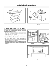
... between the Mounting Plate and the end of each of the Toggle Nuts (in position while tightening Toggle Bolts. Place carton upside down. Position oven to assist in the correct position before insertion. 5. MOUNTING PLATE 1. Insert Toggle Bolts into matched openings on Mounting Plate. 3. NOTE: Before ...more than wall thickness Wall Figure 18 Toggle Bolt Figure 19 10 PREPARATION AND USE OF THE CARTON TO ASSIST IN THE INSTALLATION OF THE MICROWAVE OVEN Utilization of the carton may make sure all of the wall. Top Side 6 Cutting Line Figure 20 See Figure 17. 4. See Figure ...
... between the Mounting Plate and the end of each of the Toggle Nuts (in position while tightening Toggle Bolts. Place carton upside down. Position oven to assist in the correct position before insertion. 5. MOUNTING PLATE 1. Insert Toggle Bolts into matched openings on Mounting Plate. 3. NOTE: Before ...more than wall thickness Wall Figure 18 Toggle Bolt Figure 19 10 PREPARATION AND USE OF THE CARTON TO ASSIST IN THE INSTALLATION OF THE MICROWAVE OVEN Utilization of the carton may make sure all of the wall. Top Side 6 Cutting Line Figure 20 See Figure 17. 4. See Figure ...
Installation Instructions
Page 7
... Cord Hanger 4. See Figure 25. See Figure 23. 2. See Figure 25. 4. Use two Tapping Screws 5 to secure the levers that are recommended to attach the Microwave Oven/Hood to the Mounting Plate. 1. Figure 22 Figure 23 3 6 5 5 Figure 24 4 Figure 25 7 Make a bundle of the Power Supply Cord and attach it onto ... Mounting Plate. Thread the Power Supply Cord through the hole made in the INSTALLATION HARDWARE, to attach the unit to the inside of the oven. See Figure 24. 3. Use two Top Cabinet Screws 3 and two Flat Washers 6, supplied in the bottom of the top cabinet. Install the...
... Cord Hanger 4. See Figure 25. See Figure 23. 2. See Figure 25. 4. Use two Tapping Screws 5 to secure the levers that are recommended to attach the Microwave Oven/Hood to the Mounting Plate. 1. Figure 22 Figure 23 3 6 5 5 Figure 24 4 Figure 25 7 Make a bundle of the Power Supply Cord and attach it onto ... Mounting Plate. Thread the Power Supply Cord through the hole made in the INSTALLATION HARDWARE, to attach the unit to the inside of the oven. See Figure 24. 3. Use two Top Cabinet Screws 3 and two Flat Washers 6, supplied in the bottom of the top cabinet. Install the...


