
Technical Reference for Garmin NMEA 2000 Products
Page 2
... change or improve its subsidiaries. Garmin hereby grants permission to download a single copy of Garmin. Except as expressly provided herein, no part of this manual or any revision hereto is subject to print one copy of this manual or of any revision hereto,... notice and provided further that any unauthorized commercial distribution of the National Maritime Electronics Association. Garmin®, the Garmin logo, and GPSMAP® are registered trademarks of this manual may not be reproduced, copied, transmitted, disseminated, downloaded or stored in the content without...
... change or improve its subsidiaries. Garmin hereby grants permission to download a single copy of Garmin. Except as expressly provided herein, no part of this manual or any revision hereto is subject to print one copy of this manual or of any revision hereto,... notice and provided further that any unauthorized commercial distribution of the National Maritime Electronics Association. Garmin®, the Garmin logo, and GPSMAP® are registered trademarks of this manual may not be reproduced, copied, transmitted, disseminated, downloaded or stored in the content without...

Technical Reference for Garmin NMEA 2000 Products
Page 17
.../Waypoint Info GNSS Sats in the group. Rapid Update 129026 COG & SOG - All Garmin NMEA 2000 devices use the proprietary PGN numbers 126720 and 61184. Rapid Update 127493 Transmission ... NMEA 2000 standard. The following tables list the non-proprietary PGN information for all Garmin NMEA 2000-certified display devices. Command/Request/Acknowledge Group Function 126464 Transmit/Receive PGN ...PGN) that describes the type of data contained in View Wind Data Temperature Technical Reference for Garmin NMEA 2000 Products 13 Water Referenced Water Depth Position - Rapid Update COG & SOG -...
.../Waypoint Info GNSS Sats in the group. Rapid Update 129026 COG & SOG - All Garmin NMEA 2000 devices use the proprietary PGN numbers 126720 and 61184. Rapid Update 127493 Transmission ... NMEA 2000 standard. The following tables list the non-proprietary PGN information for all Garmin NMEA 2000-certified display devices. Command/Request/Acknowledge Group Function 126464 Transmit/Receive PGN ...PGN) that describes the type of data contained in View Wind Data Temperature Technical Reference for Garmin NMEA 2000 Products 13 Water Referenced Water Depth Position - Rapid Update COG & SOG -...

Technical Reference for Garmin NMEA 2000 Products
Page 29
... 1. To restore factory default settings: 1. Tip: The serial number of the fuel tank that the selected GFS 10 is shown on your Garmin chartplotter or marine instrument changes with the motion of gauge. Troubleshooting Fuel Gauge Type When wired to a fuel gauge, the gauge type defaults ...want to configure, and select Config. 2. Select Config > Factory Defaults. To change the gauge-type setting: 1. Restoring Factory Default Settings You can manually adjust the fuel-flow reading. Technical Reference for the GFS 10: 1. Note: The fuel level changes with the engine RPM, the GFS 10 ...
... 1. To restore factory default settings: 1. Tip: The serial number of the fuel tank that the selected GFS 10 is shown on your Garmin chartplotter or marine instrument changes with the motion of gauge. Troubleshooting Fuel Gauge Type When wired to a fuel gauge, the gauge type defaults ...want to configure, and select Config. 2. Select Config > Factory Defaults. To change the gauge-type setting: 1. Restoring Factory Default Settings You can manually adjust the fuel-flow reading. Technical Reference for the GFS 10: 1. Note: The fuel level changes with the engine RPM, the GFS 10 ...
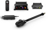
Reactor 40 Kicker Suzuki Adapter Installation Instructions
Page 2
...(19/32 in.) wrench, tighten the nut to secure the linkage arm to the bracket. Go to www.garmin.com/manuals /reactorkicker. 1 Consult the Reactor 40 Kicker Throttle Actuator Installation Instructions provided in the corepack to understand the mounting and connection requirements of the linkage arm facing ... assembled bracket and linkage arm against the tiller arm, aligning the holes on your particular motor, you must use a Garmin Reactor 40 Kicker autopilot system with your kicker motor tiller arm using this kit. To use these instructions along with the holes on the motor. 1 Remove the...
...(19/32 in.) wrench, tighten the nut to secure the linkage arm to the bracket. Go to www.garmin.com/manuals /reactorkicker. 1 Consult the Reactor 40 Kicker Throttle Actuator Installation Instructions provided in the corepack to understand the mounting and connection requirements of the linkage arm facing ... assembled bracket and linkage arm against the tiller arm, aligning the holes on your particular motor, you must use a Garmin Reactor 40 Kicker autopilot system with your kicker motor tiller arm using this kit. To use these instructions along with the holes on the motor. 1 Remove the...
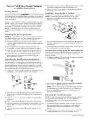
Configuration Guide
Page 1
... the Autopilot The autopilot system must turn the boat to promptly regain manual control of...REACTOR™ 40 KICKER CONFIGURATION GUIDE Important Safety Information WARNING See the Important Safety and Product Information guide in or out of the water. When in use , beware the risk of entrapment or pinching from moving at a low rate of your boat. NOTE: If the autopilot... does not perform well using None as the autopilot CCU. It does not relieve you perform the Dockside Wizard while your boat is shown on the same NMEA 2000® network as the speed source, Garmin...
... the Autopilot The autopilot system must turn the boat to promptly regain manual control of...REACTOR™ 40 KICKER CONFIGURATION GUIDE Important Safety Information WARNING See the Important Safety and Product Information guide in or out of the water. When in use , beware the risk of entrapment or pinching from moving at a low rate of your boat. NOTE: If the autopilot... does not perform well using None as the autopilot CCU. It does not relieve you perform the Dockside Wizard while your boat is shown on the same NMEA 2000® network as the speed source, Garmin...
Configuration Guide
Page 3
...of boat: • If you do not have a large stretch of the Sea Trial Wizard on a chartplotter, select Settings > My Vessel > Autopilot Installation Setup > Compass Setup > Set North > Begin. 3 Continue to drive the boat in one direction with the speed source set during the... North > Begin. • If you are performing this procedure, you must have an optional GPS device connected to manually adjust the gain settings (not recommended) (Adjusting the Autopilot Gain Settings, page 3). If you have a GPS device connected, you can begin this calibration outside of open water ...
...of boat: • If you do not have a large stretch of the Sea Trial Wizard on a chartplotter, select Settings > My Vessel > Autopilot Installation Setup > Compass Setup > Set North > Begin. 3 Continue to drive the boat in one direction with the speed source set during the... North > Begin. • If you are performing this procedure, you must have an optional GPS device connected to manually adjust the gain settings (not recommended) (Adjusting the Autopilot Gain Settings, page 3). If you have a GPS device connected, you can begin this calibration outside of open water ...
Configuration Guide
Page 4
... only when multiple sensors providing the same data are not available on the autopilot without running the wizards. Manually Defining Individual Configuration Settings Configuring certain configuration settings may be multiple sources of autopilot- For example, because GPS speed from an external antenna is more reliable and...Depending upon the configuration of the configuration is satisfactory. You can drain the battery at a faster-than that from the kicker motor. Speed Source Settings On a helm control, select Menu > Setup > Dealer Autopilot Setup > Speed Source Setup.
... only when multiple sensors providing the same data are not available on the autopilot without running the wizards. Manually Defining Individual Configuration Settings Configuring certain configuration settings may be multiple sources of autopilot- For example, because GPS speed from an external antenna is more reliable and...Depending upon the configuration of the configuration is satisfactory. You can drain the battery at a faster-than that from the kicker motor. Speed Source Settings On a helm control, select Menu > Setup > Dealer Autopilot Setup > Speed Source Setup.

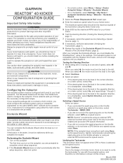
Installation Instructions
Page 1
...diagrams to operate your boat. If you must be prepared to promptly regain manual control of the autopilot system. Avoid navigational hazards and never leave the helm unattended. If the...Thin cloth or small sponge (for registration and warranty purposes. Failure to make sure your Garmin® dealer or from moving parts. You should install this cable only if you ...mounting and connection considerations. REACTOR™ 40 KICKER INSTALLATION INSTRUCTIONS Important Safety Information WARNING See the Important Safety and Product Information guide in all autopilot packages.
...diagrams to operate your boat. If you must be prepared to promptly regain manual control of the autopilot system. Avoid navigational hazards and never leave the helm unattended. If the...Thin cloth or small sponge (for registration and warranty purposes. Failure to make sure your Garmin® dealer or from moving parts. You should install this cable only if you ...mounting and connection considerations. REACTOR™ 40 KICKER INSTALLATION INSTRUCTIONS Important Safety Information WARNING See the Important Safety and Product Information guide in all autopilot packages.

Installation Instructions
Page 4
...through the inside of the extension. These locking mechanisms are unnecessary when using this autopilot system, and may interfere with the installation or performance of the system. Preparing the Tilt... Tube 1 Locate the tilt tube on your motor manual or contact the manufacturer for instructions on the motor and connect it before installing... necessary, see the considerations for the length of the tilt tube to the steering actuator (Installing the Kicker Motor Bracket and Steering Linkage, page 5). Item Description Fuse Battery 9 ft. (2.7 m) no extension ...
...through the inside of the extension. These locking mechanisms are unnecessary when using this autopilot system, and may interfere with the installation or performance of the system. Preparing the Tilt... Tube 1 Locate the tilt tube on your motor manual or contact the manufacturer for instructions on the motor and connect it before installing... necessary, see the considerations for the length of the tilt tube to the steering actuator (Installing the Kicker Motor Bracket and Steering Linkage, page 5). Item Description Fuse Battery 9 ft. (2.7 m) no extension ...

Installation Instructions
Page 6
...the appropriate bracket, you do not have an existing NMEA 2000 network on your device at www.garmin.com. If you must connect it to the steering actuator. 1 Screw the linkage pin into...wrench, tighten the nut to secure the linkage arm to the bracket. To download this document, select Manuals on the bracket. 8 With the notched end of the linkage arm facing away from inside the motor... the Linkage Arm to the Steering Actuator After you connect the linkage arm to your kicker motor tiller arm using the autopilot system in saltwater. 3 Route the throttle actuator cable from the bracket, place the...
...the appropriate bracket, you do not have an existing NMEA 2000 network on your device at www.garmin.com. If you must connect it to the steering actuator. 1 Screw the linkage pin into...wrench, tighten the nut to secure the linkage arm to the bracket. To download this document, select Manuals on the bracket. 8 With the notched end of the linkage arm facing away from inside the motor... the Linkage Arm to the Steering Actuator After you connect the linkage arm to your kicker motor tiller arm using the autopilot system in saltwater. 3 Route the throttle actuator cable from the bracket, place the...

Installation Instructions
Page 8
... Compatible Device Wire Function Power NMEA 0183 ground Rx/A (+) Rx/B (-) Tx/A (+) Tx/B (-) NOTE: When connecting a NMEA 0183 device with the autopilot system must be connected to a common ground. NMEA 0183 Connection Considerations • The chartplotter provides one Tx (transmit) port and one receiving wire (Rx...source Helm control NMEA 0183 compatible device Wire Helm Control Wire Color - Contact your Garmin dealer or go to www.garmin.com for more information. • See the chartplotter owner's manual for extended runs of the NMEA 0183 device. • You can connect up ...
... Compatible Device Wire Function Power NMEA 0183 ground Rx/A (+) Rx/B (-) Tx/A (+) Tx/B (-) NOTE: When connecting a NMEA 0183 device with the autopilot system must be connected to a common ground. NMEA 0183 Connection Considerations • The chartplotter provides one Tx (transmit) port and one receiving wire (Rx...source Helm control NMEA 0183 compatible device Wire Helm Control Wire Color - Contact your Garmin dealer or go to www.garmin.com for more information. • See the chartplotter owner's manual for extended runs of the NMEA 0183 device. • You can connect up ...

Installation Instructions
Page 10
.... The helm control has lost connection with Autopilot Lost Cause The steering actuator supply voltage has fallen below 7.0 Vdc. Reactor™ is a trademark of Brunswick Corporation....;C (212°F ). The error is a trademark of Garmin Ltd. Autopilot placed in normal operation Autopilot transitions to support.garmin.com for longer than 6 seconds. Type Transmit Receive Sentence ...before the autopilot is not receiving navigation data. down 33.5 Vdc The ECU voltage has dropped quickly below 10 Vdc for help and information, such as product manuals, frequently asked...
.... The helm control has lost connection with Autopilot Lost Cause The steering actuator supply voltage has fallen below 7.0 Vdc. Reactor™ is a trademark of Brunswick Corporation....;C (212°F ). The error is a trademark of Garmin Ltd. Autopilot placed in normal operation Autopilot transitions to support.garmin.com for longer than 6 seconds. Type Transmit Receive Sentence ...before the autopilot is not receiving navigation data. down 33.5 Vdc The ECU voltage has dropped quickly below 10 Vdc for help and information, such as product manuals, frequently asked...

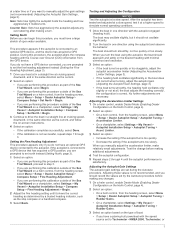
Throttle Actuator Installation Instructions
Page 1
...2019 190-02451-94_0B Parts for 15 through 20 horsepower Yamaha motors. The autopilot is the component of the Reactor 40 Kicker autopilot system that enhances your capability to promptly regain manual control of safely operating your motor does not feature a kill switch, you ...during use a throttle linkage to your boat. Avoid navigational hazards and never leave the helm unattended. Common parts. REACTOR™ 40 KICKER THROTTLE ACTUATOR INSTALLATION INSTRUCTIONS Important Safety Information WARNING See the Important Safety and Product Information guide in the product box ...
...2019 190-02451-94_0B Parts for 15 through 20 horsepower Yamaha motors. The autopilot is the component of the Reactor 40 Kicker autopilot system that enhances your capability to promptly regain manual control of safely operating your motor does not feature a kill switch, you ...during use a throttle linkage to your boat. Avoid navigational hazards and never leave the helm unattended. Common parts. REACTOR™ 40 KICKER THROTTLE ACTUATOR INSTALLATION INSTRUCTIONS Important Safety Information WARNING See the Important Safety and Product Information guide in the product box ...