
Technical Reference for Garmin NMEA 2000 Products
Page 3
...included in a Sensor Configuration Guide provided with each Garmin NMEA 2000-certified sensor. • At the end is also included in -country support information, or contact Garmin (Europe) Ltd. Use this checklist when installing a NMEA 2000 network to help you determine which ...NMEA 2000 sensors provide the particular data type you experience difficulty installing a NMEA 2000 network, or have correctly followed ...
...included in a Sensor Configuration Guide provided with each Garmin NMEA 2000-certified sensor. • At the end is also included in -country support information, or contact Garmin (Europe) Ltd. Use this checklist when installing a NMEA 2000 network to help you determine which ...NMEA 2000 sensors provide the particular data type you experience difficulty installing a NMEA 2000 network, or have correctly followed ...

Technical Reference for Garmin NMEA 2000 Products
Page 4
Table of Contents Table of Contents Introduction...iii Contact Garmin...iii NMEA 2000 Fundamentals...1 Garmin NMEA 2000 Device Overview...1 Building a NMEA 2000 Network...3 Existing NMEA 2000 Installation Considerations...8 NMEA 2000 Glossary...8 General NMEA 2000 Data Type Requirements...9 NMEA 2000-Certified Display Device PGN Information...13...Speed and Temperature Adapter)...19 Intelliducer (Intelligent Depth Transducer-Transom Mount and Thru-Hull)...19 GWS 10 (Garmin Wind Sensor)...20 GHP 10 (Marine Autopilot System)...20 GXM 51...21 VHF 200...21 VHF 300...21 AIS 300...22 AIS 600...22 NMEA ...
Table of Contents Table of Contents Introduction...iii Contact Garmin...iii NMEA 2000 Fundamentals...1 Garmin NMEA 2000 Device Overview...1 Building a NMEA 2000 Network...3 Existing NMEA 2000 Installation Considerations...8 NMEA 2000 Glossary...8 General NMEA 2000 Data Type Requirements...9 NMEA 2000-Certified Display Device PGN Information...13...Speed and Temperature Adapter)...19 Intelliducer (Intelligent Depth Transducer-Transom Mount and Thru-Hull)...19 GWS 10 (Garmin Wind Sensor)...20 GHP 10 (Marine Autopilot System)...20 GXM 51...21 VHF 200...21 VHF 300...21 AIS 300...22 AIS 600...22 NMEA ...
Technical Reference for Garmin NMEA 2000 Products
Page 5
...GFS 10) In the sample box diagram, a complete NMEA 2000 network is included with a Garmin GFS 10 fuel sensor. In this guide will help you would like to verify the installation. Garmin sensors may also include additional NMEA 2000 components (such as shown by the shaded components in... the product documentation. If you do not have installed your boat already contains a NMEA 2000 network and you ...
...GFS 10) In the sample box diagram, a complete NMEA 2000 network is included with a Garmin GFS 10 fuel sensor. In this guide will help you would like to verify the installation. Garmin sensors may also include additional NMEA 2000 components (such as shown by the shaded components in... the product documentation. If you do not have installed your boat already contains a NMEA 2000 network and you ...
Technical Reference for Garmin NMEA 2000 Products
Page 6
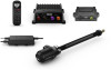
...T-connectors are used to nearby lightning strikes, but it is not responsible for Garmin NMEA 2000 Products Male* (not pictured) 010-11094-00 Field-installable connector - Garmin is not able to shorten any Garmin NMEA 2000 drop/backbone cable. ** The gray in -line lightning arrestor**... (not pictured) 010-11171-02 * The field-installable connectors are interchangeable. NMEA 2000 Fundamentals NMEA 2000...
...T-connectors are used to nearby lightning strikes, but it is not responsible for Garmin NMEA 2000 Products Male* (not pictured) 010-11094-00 Field-installable connector - Garmin is not able to shorten any Garmin NMEA 2000 drop/backbone cable. ** The gray in -line lightning arrestor**... (not pictured) 010-11171-02 * The field-installable connectors are interchangeable. NMEA 2000 Fundamentals NMEA 2000...

Technical Reference for Garmin NMEA 2000 Products
Page 7
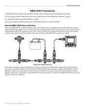
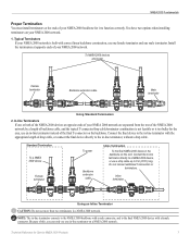
... termination (page 7) • Cable length and device limits (page 8) Technical Reference for the network to function correctly. Consult the installation instructions for each device (Load Equivalency Number) Fuel sensor Marine instrument Chartplotter Intelligent transducer Ignition or in-line switch Fuse Female terminator +... NMEA 2000 backbone must be connected to power, and terminators must follow certain rules to be sure you must be installed at both ends for Garmin NMEA 2000 Products 3 When you design a NMEA 2000 network, start by the NMEA 2000 network; When building ...
... termination (page 7) • Cable length and device limits (page 8) Technical Reference for the network to function correctly. Consult the installation instructions for each device (Load Equivalency Number) Fuel sensor Marine instrument Chartplotter Intelligent transducer Ignition or in-line switch Fuse Female terminator +... NMEA 2000 backbone must be connected to power, and terminators must follow certain rules to be sure you must be installed at both ends for Garmin NMEA 2000 Products 3 When you design a NMEA 2000 network, start by the NMEA 2000 network; When building ...
Technical Reference for Garmin NMEA 2000 Products
Page 8
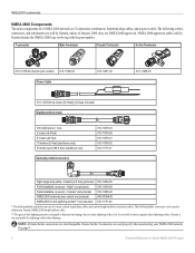
.... To NMEA 2000 devices and power Female terminator CORRECT Backbone extension cable Male terminator T-connector installed incorrectly Male terminator (also installed incorrectly) Correct Linear Backbone Construction To NMEA 2000 devices and power INCORRECT Backbone extension cable Male... terminator Incorrect Linear Backbone Construction 4 Technical Reference for Garmin NMEA 2000 Products Although the male and female connectors...
.... To NMEA 2000 devices and power Female terminator CORRECT Backbone extension cable Male terminator T-connector installed incorrectly Male terminator (also installed incorrectly) Correct Linear Backbone Construction To NMEA 2000 devices and power INCORRECT Backbone extension cable Male... terminator Incorrect Linear Backbone Construction 4 Technical Reference for Garmin NMEA 2000 Products Although the male and female connectors...

Technical Reference for Garmin NMEA 2000 Products
Page 9
... voltage source, such as the ground (black) wire. You can connect power to either at the end. The Garmin NMEA 2000 power cable connects to the battery and install an in-line switch. Do not connect your NMEA 2000 network to your network use this example, we see that...where to place the power cable and the T-connector on your NMEA 2000 network, you will depend on your NMEA 2000 network, contact a professional installer. Examples The following examples show a correctly designed, end-powered NMEA 2000 network; To determine the voltage drop in your NMEA 2000 network, use power...
... voltage source, such as the ground (black) wire. You can connect power to either at the end. The Garmin NMEA 2000 power cable connects to the battery and install an in-line switch. Do not connect your NMEA 2000 network to your network use this example, we see that...where to place the power cable and the T-connector on your NMEA 2000 network, you will depend on your NMEA 2000 network, contact a professional installer. Examples The following examples show a correctly designed, end-powered NMEA 2000 network; To determine the voltage drop in your NMEA 2000 network, use power...
Technical Reference for Garmin NMEA 2000 Products
Page 11
...: Do not use an in -line terminator, without a drop cable. Typical Terminators If your NMEA 2000 network is too bulky for Garmin NMEA 2000 Products 7 Standard Termination To a NMEA 2000 device Female terminator To power Backbone extension cable Inline Termination To the final NMEA ...is built with correct linear backbone construction, use one male terminator. Do not connect additional T-connectors or terminators. Because of this end. Install the terminators at opposite ends of your NMEA 2000 network. 1. Connect the final device to the in -line terminator on your NMEA 2000...
...: Do not use an in -line terminator, without a drop cable. Typical Terminators If your NMEA 2000 network is too bulky for Garmin NMEA 2000 Products 7 Standard Termination To a NMEA 2000 device Female terminator To power Backbone extension cable Inline Termination To the final NMEA ...is built with correct linear backbone construction, use one male terminator. Do not connect additional T-connectors or terminators. Because of this end. Install the terminators at opposite ends of your NMEA 2000 network. 1. Connect the final device to the in -line terminator on your NMEA 2000...

Technical Reference for Garmin NMEA 2000 Products
Page 12
... can be connected through a switch (instead of the NMEA 2000 network. Existing NMEA 2000 Installation Considerations If your boat has an existing NMEA 2000 installation, and you would like to add Garmin NMEA 2000 equipment, there are a few things to function correctly. A NMEA 2000 network...)-A number that connects to your NMEA 2000 network. Each device should be connected to the NMEA 2000 network. Termination: Are terminators installed on the boat. A backbone cable extends the NMEA 2000 backbone to use NMEA 2000 mini connectors and cables in mind these considerations...
... can be connected through a switch (instead of the NMEA 2000 network. Existing NMEA 2000 Installation Considerations If your boat has an existing NMEA 2000 installation, and you would like to add Garmin NMEA 2000 equipment, there are a few things to function correctly. A NMEA 2000 network...)-A number that connects to your NMEA 2000 network. Each device should be connected to the NMEA 2000 network. Termination: Are terminators installed on the boat. A backbone cable extends the NMEA 2000 backbone to use NMEA 2000 mini connectors and cables in mind these considerations...

Technical Reference for Garmin NMEA 2000 Products
Page 13
...Sensor Garmin Chartplotter and GPS Antenna Garmin Chartplotter and GPS Antenna Garmin Chartplotter Garmin Chartplotter and GPS Antenna Garmin Chartplotter and GPS Antenna Garmin Chartplotter and GPS Antenna Garmin ...Chartplotter and GPS Antenna Heading Sensor GPS Antenna Technical Reference for a list of sensors may provide more about PGN information, see page 18. and the NMEA 2000 sensor that you have installed...
...Sensor Garmin Chartplotter and GPS Antenna Garmin Chartplotter and GPS Antenna Garmin Chartplotter Garmin Chartplotter and GPS Antenna Garmin Chartplotter and GPS Antenna Garmin Chartplotter and GPS Antenna Garmin ...Chartplotter and GPS Antenna Heading Sensor GPS Antenna Technical Reference for a list of sensors may provide more about PGN information, see page 18. and the NMEA 2000 sensor that you have installed...

Technical Reference for Garmin NMEA 2000 Products
Page 28
...to configure. 2. Select Config > Level Calibration > Reset Calibration. 24 Technical Reference for fuel-level information. Using Fuel-Level Information With a Garmin Chartplotter or Marine Instrument To receive fuel-level information, connect the wiring harness on the NMEA 2000 device configuration menu, select the GFS 10 ... to the fuel tank you fill up the tank. To specify the amount of each time you add fuel to the GFS 10 Installation Instructions. While viewing the NMEA 2000 device configuration menu, select the GFS 10 device that is used on your NMEA 2000 device,...
...to configure. 2. Select Config > Level Calibration > Reset Calibration. 24 Technical Reference for fuel-level information. Using Fuel-Level Information With a Garmin Chartplotter or Marine Instrument To receive fuel-level information, connect the wiring harness on the NMEA 2000 device configuration menu, select the GFS 10 ... to the fuel tank you fill up the tank. To specify the amount of each time you add fuel to the GFS 10 Installation Instructions. While viewing the NMEA 2000 device configuration menu, select the GFS 10 device that is used on your NMEA 2000 device,...

Technical Reference for Garmin NMEA 2000 Products
Page 29
... Settings You can manually adjust the fuel-flow reading. Select Config > Factory Defaults. To configure tank and engine information for a multi-tank installation, assign the selected GFS 10 to a specific tank. • Tank Capacity-define the fuel capacity of 20 gal./hr. (75 L/h) would..., select the GFS 10 device. 2. Technical Reference for Garmin NMEA 2000 Products 25 Troubleshooting the Fuel-Flow Reading If the fuel-flow information received from the following options: • Engine Number-for a multi-engine installation, assign the selected GFS 10 to configure, and select Config...
... Settings You can manually adjust the fuel-flow reading. Select Config > Factory Defaults. To configure tank and engine information for a multi-tank installation, assign the selected GFS 10 to a specific tank. • Tank Capacity-define the fuel capacity of 20 gal./hr. (75 L/h) would..., select the GFS 10 device. 2. Technical Reference for Garmin NMEA 2000 Products 25 Troubleshooting the Fuel-Flow Reading If the fuel-flow information received from the following options: • Engine Number-for a multi-engine installation, assign the selected GFS 10 to configure, and select Config...

Technical Reference for Garmin NMEA 2000 Products
Page 40
...the keel offset: 1. Keel Offset GWS 10 (Garmin Wind Sensor) Configuring the Wind Angle Offset (Orientation) When mounting the sensor, you must adjust the angle offset if you are measuring up to the water line (Intelliducer installed on the starboard side of the boat, and 270... Configuring the Wind Speed Filter The wind speed filter governs how quickly the NMEA 2000-compatible display device shows a change in the GWS 10 Installation Instructions. While viewing the NMEA 2000 device information, select Config > Wind Angle Offset. 2. For example, 90 degrees is on the keel), ...
...the keel offset: 1. Keel Offset GWS 10 (Garmin Wind Sensor) Configuring the Wind Angle Offset (Orientation) When mounting the sensor, you must adjust the angle offset if you are measuring up to the water line (Intelliducer installed on the starboard side of the boat, and 270... Configuring the Wind Speed Filter The wind speed filter governs how quickly the NMEA 2000-compatible display device shows a change in the GWS 10 Installation Instructions. While viewing the NMEA 2000 device information, select Config > Wind Angle Offset. 2. For example, 90 degrees is on the keel), ...
Technical Reference for Garmin NMEA 2000 Products
Page 42
... power connected through the ignition switch-if not, did you install a switch? (page 5) Is the NMEA 2000 power cable grounded? Is the NMEA 2000 network connected to confirm your Garmin products, visit the Garmin Web site at www.garmin.com. March 2012 © 2009-2012 Garmin Ltd. Liberty House, Hounsdown Business Park, Southampton, Hampshire, SO40...
... power connected through the ignition switch-if not, did you install a switch? (page 5) Is the NMEA 2000 power cable grounded? Is the NMEA 2000 network connected to confirm your Garmin products, visit the Garmin Web site at www.garmin.com. March 2012 © 2009-2012 Garmin Ltd. Liberty House, Hounsdown Business Park, Southampton, Hampshire, SO40...

?Important Safety and Product Information
Page 2
...no warranty as the real-time clock. Within this warranty is covered under applicable law in a particular installation. In addition, Garmin reserves the right to refuse warranty claims against harmful interference in the device only to facilitate, not ...to all available navigation sources, including information from the responsibility of the vessel. Garmin makes no guarantee that fail in normal use the electronic chart in a residential installation. IN NO EVENT SHALL Garmin BE LIABLE FOR ANY INCIDENTAL, SPECIAL, INDIRECT, OR CONSEQUENTIAL DAMAGES, WHETHER RESULTING...
...no warranty as the real-time clock. Within this warranty is covered under applicable law in a particular installation. In addition, Garmin reserves the right to refuse warranty claims against harmful interference in the device only to facilitate, not ...to all available navigation sources, including information from the responsibility of the vessel. Garmin makes no guarantee that fail in normal use the electronic chart in a residential installation. IN NO EVENT SHALL Garmin BE LIABLE FOR ANY INCIDENTAL, SPECIAL, INDIRECT, OR CONSEQUENTIAL DAMAGES, WHETHER RESULTING...

Reactor 40 Kicker Mercury 8 through 99 HP Installation Examples
Page 1
... throttle actuators. The provided photos are examples, and may need to your motor when removing the tiller lock or installing this product. NOTE: If your Reactor 40 Kicker and Mercury 8 through 9.9 HP motor. Remove the bolts ➋ to help when following the instructions included with...not responsible for damage caused to consult your motor. Removing the Tiller Lock Complete Steering Actuator Installation Steering Actuator Spacer Stack Order April 2020 © 2020 Garmin Ltd. or its subsidiaries 190-02451-24_0A Printed in Taiwan For further information, you may...
... throttle actuators. The provided photos are examples, and may need to your motor when removing the tiller lock or installing this product. NOTE: If your Reactor 40 Kicker and Mercury 8 through 9.9 HP motor. Remove the bolts ➋ to help when following the instructions included with...not responsible for damage caused to consult your motor. Removing the Tiller Lock Complete Steering Actuator Installation Steering Actuator Spacer Stack Order April 2020 © 2020 Garmin Ltd. or its subsidiaries 190-02451-24_0A Printed in Taiwan For further information, you may...

Reactor 40 Kicker Mercury 8 through 99 HP Installation Examples
Page 2
Excess RPM cable must be replaced with moving parts. RPM Cable Installed on Spark Plug Cable Exterior RPM Cable NOTE: The RPM cable cannot be secured inside the cowling in a location that does not interfere with the new linkage rod ➊ in Taiwan or its subsidiaries 190-02451-24_0A Printed in parts bag 3. April 2020 © 2020 Garmin Ltd. Throttle Actuator Installation Examples Complete Throttle Installation NOTE: The existing tiller throttle linkage rod must be shortened.
Excess RPM cable must be replaced with moving parts. RPM Cable Installed on Spark Plug Cable Exterior RPM Cable NOTE: The RPM cable cannot be secured inside the cowling in a location that does not interfere with the new linkage rod ➊ in Taiwan or its subsidiaries 190-02451-24_0A Printed in parts bag 3. April 2020 © 2020 Garmin Ltd. Throttle Actuator Installation Examples Complete Throttle Installation NOTE: The existing tiller throttle linkage rod must be shortened.

Reactor 40 Kicker Mercury EFI Installation Examples
Page 1
... Lock Remove the tiller lock assembly ➌ before installing the steering actuator. Remove the bolts ➋ to consult your Reactor 40 Kicker and Mercury EFI motor. or its subsidiaries 190-02451-25_0A Printed in Taiwan Garmin is not responsible for guidance. Steering Actuator Installation Examples Reactor™ 40 Kicker Mercury EFI Installation Examples You can use caution when disassembling the...
... Lock Remove the tiller lock assembly ➌ before installing the steering actuator. Remove the bolts ➋ to consult your Reactor 40 Kicker and Mercury EFI motor. or its subsidiaries 190-02451-25_0A Printed in Taiwan Garmin is not responsible for guidance. Steering Actuator Installation Examples Reactor™ 40 Kicker Mercury EFI Installation Examples You can use caution when disassembling the...

Reactor 40 Kicker Mercury EFI Installation Examples
Page 2
...RPM cable must be replaced with linkage from bag A ➊. April 2020 © 2020 Garmin Ltd. Throttle Actuator Installation Examples RPM Cable Installed on Spark Plug Cable Exterior Complete Throttle Installation NOTE: The existing linkage must be secured inside the cowling in a location that does not ...interfere with moving parts. Complete RPM Cable Installation RPM Cable NOTE: The RPM cable cannot be replaced with the new linkage rod...
...RPM cable must be replaced with linkage from bag A ➊. April 2020 © 2020 Garmin Ltd. Throttle Actuator Installation Examples RPM Cable Installed on Spark Plug Cable Exterior Complete Throttle Installation NOTE: The existing linkage must be secured inside the cowling in a location that does not ...interfere with moving parts. Complete RPM Cable Installation RPM Cable NOTE: The RPM cable cannot be replaced with the new linkage rod...

Reactor 40 Kicker Suzuki Adapter Installation Instructions
Page 1
... USA and other countries. or its subsidiaries, registered in the U.S. Suzuki™ is a trademark of Garmin Ltd. Reactor™ is a trademark of Garmin. December 2019 190-02451-10_0A and elsewhere. REACTOR™ 40 KICKER SUZUKI™ADAPTER Installation Instructions 2 Installationsvejledning 23 Instructions d'installation 5 Asennusohjeet 26 Istruzioni di installazione 8 Installeringsinstruksjoner 29 Installationsanweisungen 11 Installationsinstruktioner 31 Instrucciones de instalació...
... USA and other countries. or its subsidiaries, registered in the U.S. Suzuki™ is a trademark of Garmin Ltd. Reactor™ is a trademark of Garmin. December 2019 190-02451-10_0A and elsewhere. REACTOR™ 40 KICKER SUZUKI™ADAPTER Installation Instructions 2 Installationsvejledning 23 Instructions d'installation 5 Asennusohjeet 26 Istruzioni di installazione 8 Installeringsinstruksjoner 29 Installationsanweisungen 11 Installationsinstruktioner 31 Instrucciones de instalació...
