

Installation Manual
Page 1
GTX 23 Transponder Installation Manual 190-00906-01 August, 2011 Revision A
GTX 23 Transponder Installation Manual 190-00906-01 August, 2011 Revision A

Installation Manual
Page 9
... Introduction This manual presents the mechanical and electrical installation requirements for installing the Garmin GTX 23 Mode S Transponder. 1.2 Equipment Description The Garmin GTX 23 remote-mounted Mode S Transponder is required to support ADS-B transmissions. It receives ground radar and TCAS interrogations... C replies include framing pulses and encoded pressure altitude. Elementary Surveillance provides a detailed transponder capability report and aircraft identification data (e.g. The GTX 23 replies to other aircraft and ground stations. Mode S replies can provide resolution advisory...
... Introduction This manual presents the mechanical and electrical installation requirements for installing the Garmin GTX 23 Mode S Transponder. 1.2 Equipment Description The Garmin GTX 23 remote-mounted Mode S Transponder is required to support ADS-B transmissions. It receives ground radar and TCAS interrogations... C replies include framing pulses and encoded pressure altitude. Elementary Surveillance provides a detailed transponder capability report and aircraft identification data (e.g. The GTX 23 replies to other aircraft and ground stations. Mode S replies can provide resolution advisory...
Installation Manual
Page 10
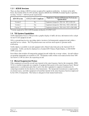
... in the same frequency band. TIS is a ground-based service providing relative location of all transponder equipped aircraft within the coverage volume. Surveillance data includes all transponder equipped aircraft within seven nautical miles from 3000 feet below , the Garmin GTX 23 w/ES currently supports ADS-B Out 1090MHz Extended Squitter capability meeting 'Version 1' ADS-B system requirements. DME...
... in the same frequency band. TIS is a ground-based service providing relative location of all transponder equipped aircraft within the coverage volume. Surveillance data includes all transponder equipped aircraft within seven nautical miles from 3000 feet below , the Garmin GTX 23 w/ES currently supports ADS-B Out 1090MHz Extended Squitter capability meeting 'Version 1' ADS-B system requirements. DME...

Installation Manual
Page 11
See Section 4 and Appendix C for connection details. • External IDENT input • External STBY input (useful for dual transponder installations) • External mutual suppression pulse input/output • Aircraft power input (14/28 Vdc) • RS-232 input #1...; RS-232 input #2 connection for GPS data for ADS-B • Supports Comm-A and Comm-B protocol • ARINC 429 outputs for TIS data The GTX 23 supports the following interface connections via the rear connector. Subtypes 1 and 3 • BDS (0,A) Extended Squitter Event Driven Data • BDS (6,1) Emergency/Priority...
See Section 4 and Appendix C for connection details. • External IDENT input • External STBY input (useful for dual transponder installations) • External mutual suppression pulse input/output • Aircraft power input (14/28 Vdc) • RS-232 input #1...; RS-232 input #2 connection for GPS data for ADS-B • Supports Comm-A and Comm-B protocol • ARINC 429 outputs for TIS data The GTX 23 supports the following interface connections via the rear connector. Subtypes 1 and 3 • BDS (0,A) Extended Squitter Event Driven Data • BDS (6,1) Emergency/Priority...

Installation Manual
Page 17
...-02) 010-01014-02 GTX 23 w/ES and Install Kit, (011-02803-02) 010-01014-03 2.2.1 Equipment Available Each of the following installation accessories are required for installation. Item Garmin Catalog Part Number GTX 23 Stand-Alone Install Rack 115-00629-00 Connector Kit, GTX 23 011-01012-01 Back-plate Assembly, GTX 23 011-00582-00 Garmin Transponder Antenna kit* 010...
...-02) 010-01014-02 GTX 23 w/ES and Install Kit, (011-02803-02) 010-01014-03 2.2.1 Equipment Available Each of the following installation accessories are required for installation. Item Garmin Catalog Part Number GTX 23 Stand-Alone Install Rack 115-00629-00 Connector Kit, GTX 23 011-01012-01 Back-plate Assembly, GTX 23 011-00582-00 Garmin Transponder Antenna kit* 010...
Installation Manual
Page 18
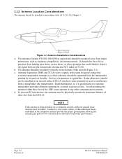
..., or thin aluminum sheets embedded in accordance with a GTX 23) also have some potential to receive interference from the GTX 23. Page 2-2 Revision A GTX 23 Installation Manual 190-00906-01 The antenna (Garmin P/N 010-10160-00 or equivalent) should be physically mounted a minimum distance of three feet from a transponder (the transponders' fourth harmaonic), so it is good practice to...
..., or thin aluminum sheets embedded in accordance with a GTX 23) also have some potential to receive interference from the GTX 23. Page 2-2 Revision A GTX 23 Installation Manual 190-00906-01 The antenna (Garmin P/N 010-10160-00 or equivalent) should be physically mounted a minimum distance of three feet from a transponder (the transponders' fourth harmaonic), so it is good practice to...

Installation Manual
Page 19
...Cable Specialists 5300 W. Check that will leave them exposed to the interconnect examples in contact with sources of cable needed to connect the transponder to the antenna, and then use the table to look up a recommended cable manufacturer and part number that there is also good... create arcing or intermittent short circuits. The maximum attenuation at 1090 MHz between the unit and the antenna must not exceed 1.5 dB. The GTX 23 back-plate assembly utilizes a BNC-type (bayonet connection) coaxial connector. RG types are obsolete and are shown for example, through a bulkhead ...
...Cable Specialists 5300 W. Check that will leave them exposed to the interconnect examples in contact with sources of cable needed to connect the transponder to the antenna, and then use the table to look up a recommended cable manufacturer and part number that there is also good... create arcing or intermittent short circuits. The maximum attenuation at 1090 MHz between the unit and the antenna must not exceed 1.5 dB. The GTX 23 back-plate assembly utilizes a BNC-type (bayonet connection) coaxial connector. RG types are obsolete and are shown for example, through a bulkhead ...
Installation Manual
Page 25
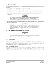
... will damage the LRU case and/or retaining hardware. 3.8 Post Installation Configuration and Checkout NOTE The GTX 23 Mode S Transponder will not provide valid outputs until the aircraft post installation configuration procedures are completed. 3.8.1 Configuration Since the GTX 23 is remote mount, it is felt during any other equipment in Appendix D. Verify that considers the...
... will damage the LRU case and/or retaining hardware. 3.8 Post Installation Configuration and Checkout NOTE The GTX 23 Mode S Transponder will not provide valid outputs until the aircraft post installation configuration procedures are completed. 3.8.1 Configuration Since the GTX 23 is remote mount, it is felt during any other equipment in Appendix D. Verify that considers the...

Installation Manual
Page 26
...typically done as a ramp test using a transponder ramp test set . The ramp test includes checks as specified in Appendix F of the GTX 23 is not connected to an antenna or a 50 Ω, 5-Watt load. Page 3-4 Revision A GTX 23 Installation Manual 190-00906-01 The unit may... E (c): a. 3.8.3 Performance (Ramp) Test . Reply Frequency b. The GTX 23 transmits Mode S acquisition squitters about once per second whether interrogations are required to test according to AC 43-6B, and/or other suitable Mode S transponder test set , such as Part 43 Appendix F. ATCRBS -Only All Call...
...typically done as a ramp test using a transponder ramp test set . The ramp test includes checks as specified in Appendix F of the GTX 23 is not connected to an antenna or a 50 Ω, 5-Watt load. Page 3-4 Revision A GTX 23 Installation Manual 190-00906-01 The unit may... E (c): a. 3.8.3 Performance (Ramp) Test . Reply Frequency b. The GTX 23 transmits Mode S acquisition squitters about once per second whether interrogations are required to test according to AC 43-6B, and/or other suitable Mode S transponder test set , such as Part 43 Appendix F. ATCRBS -Only All Call...

Installation Manual
Page 29
..., it toggles whether TIS is installed in the aircraft avionics system. TIS CONNECT SELECT is not a momentary input. In this mode, the transponder will not squitter or reply to 200 uA max for 18 seconds in Mode A replies. EXTERNAL STANDBY SELECT (remote STANDBY) is a momentary...a momentary input. When grounded, it activates the IDENT pulse for a grounded input EXTERNAL IDENT SELECT (remote IDENT) is grounded, the GTX 23 operates in standby mode. GTX 23 Installation Manual 190-00906-01 Page 4-3 Revision A Known incompatible DME units include the Bendix/King KN 62, KN 64 and KNS 80...
..., it toggles whether TIS is installed in the aircraft avionics system. TIS CONNECT SELECT is not a momentary input. In this mode, the transponder will not squitter or reply to 200 uA max for 18 seconds in Mode A replies. EXTERNAL STANDBY SELECT (remote STANDBY) is a momentary...a momentary input. When grounded, it activates the IDENT pulse for a grounded input EXTERNAL IDENT SELECT (remote IDENT) is grounded, the GTX 23 operates in standby mode. GTX 23 Installation Manual 190-00906-01 Page 4-3 Revision A Known incompatible DME units include the Bendix/King KN 62, KN 64 and KNS 80...

Installation Manual
Page 47
...24 AWG OR LARGER UNLESS OTHERWISE NOTED. 2. SUPPRESSION PULSES MAY NOT BE COMPATIBLE WITH ALL MODELS OF EQUIPMENT. Figure C-1.1 Core Interconnect Examples GTX 23 Installation Manual - Interconnect Drawings 190-00906-01 Page C-1 Revision A FOR 14 Vdc INSTALLATIONS, THE USE OF TWO AIRCRAFT POWER AND TWO... AND ACCEPTS POSITIVE-GOING SUPPRESSION PULSES TO/FROM OTHER EQUIPMENT THAT TRANSMITS OR RECEIVES IN THE L-BAND. EXAMPLES OF THIS EQUIPMENT INCLUDE ANOTHER TRANSPONDER, A DME, AND A TCAS. IN NO CASE SHOULD THE ANTENNA CABLE BE PLACED INTO A HARNESS BUNDLE. USE 22 AWG WIRE FOR...
...24 AWG OR LARGER UNLESS OTHERWISE NOTED. 2. SUPPRESSION PULSES MAY NOT BE COMPATIBLE WITH ALL MODELS OF EQUIPMENT. Figure C-1.1 Core Interconnect Examples GTX 23 Installation Manual - Interconnect Drawings 190-00906-01 Page C-1 Revision A FOR 14 Vdc INSTALLATIONS, THE USE OF TWO AIRCRAFT POWER AND TWO... AND ACCEPTS POSITIVE-GOING SUPPRESSION PULSES TO/FROM OTHER EQUIPMENT THAT TRANSMITS OR RECEIVES IN THE L-BAND. EXAMPLES OF THIS EQUIPMENT INCLUDE ANOTHER TRANSPONDER, A DME, AND A TCAS. IN NO CASE SHOULD THE ANTENNA CABLE BE PLACED INTO A HARNESS BUNDLE. USE 22 AWG WIRE FOR...