Installation Manual
Page 4
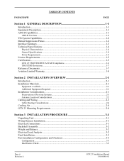
......2-1 Preservation of Previous Systems 2-1 Antenna Location Considerations 2-2 Cabling and Wiring ...2-3 Cable Routing Considerations ...2-4 Cooling Air...2-4 GTX 23 Mounting Requirements 2-4 Section 3 INSTALLATION PROCEDURE 3-1 Unpacking Unit ...3-1 Wiring Harness Installation...3-1 Electrical Connections ...3-1 Backshell Assembly ...3-2 Weight and Balance ...3-2 Electrical Load Analysis ...3-2 Final Installation...3-3 Post Installation Configuration and Checkout 3-3 Configuration ...3-3 Interference Check ...3-3 Page ii Revision A GTX 23 Installation Manual 190-00906-01
......2-1 Preservation of Previous Systems 2-1 Antenna Location Considerations 2-2 Cabling and Wiring ...2-3 Cable Routing Considerations ...2-4 Cooling Air...2-4 GTX 23 Mounting Requirements 2-4 Section 3 INSTALLATION PROCEDURE 3-1 Unpacking Unit ...3-1 Wiring Harness Installation...3-1 Electrical Connections ...3-1 Backshell Assembly ...3-2 Weight and Balance ...3-2 Electrical Load Analysis ...3-2 Final Installation...3-3 Post Installation Configuration and Checkout 3-3 Configuration ...3-3 Interference Check ...3-3 Page ii Revision A GTX 23 Installation Manual 190-00906-01

Installation Manual
Page 5
...-Quick Term B-9 Daisy Chain between Methods A and B B-10 Splicing Signal Wires...B-10 Appendix C External Interface Drawings (Example Only C-1 Appendix D Assembly and Installation Drawings D-1 GTX 23 Installation Manual 190-00906-01 Page iii Revision A Performance (Ramp) Test ...3-4 Continued Airworthiness ...3-4 Section 4 SYSTEM INTERCONNECTS 4-1 Pin Function List ...4-1 P2301 ...4-1 Aircraft Power...4-2 Discrete Functions...4-3 Discrete Outputs...4-3 Discrete Inputs ...4-3 Serial Data Electrical Characteristics 4-4 RS-232 Input/Output...4-4 ARINC 429 Input/Output ...4-4 RS-232 Input...
...-Quick Term B-9 Daisy Chain between Methods A and B B-10 Splicing Signal Wires...B-10 Appendix C External Interface Drawings (Example Only C-1 Appendix D Assembly and Installation Drawings D-1 GTX 23 Installation Manual 190-00906-01 Page iii Revision A Performance (Ramp) Test ...3-4 Continued Airworthiness ...3-4 Section 4 SYSTEM INTERCONNECTS 4-1 Pin Function List ...4-1 P2301 ...4-1 Aircraft Power...4-2 Discrete Functions...4-3 Discrete Outputs...4-3 Discrete Inputs ...4-3 Serial Data Electrical Characteristics 4-4 RS-232 Input/Output...4-4 ARINC 429 Input/Output ...4-4 RS-232 Input...

Installation Manual
Page 6
...115-00629-00 2-5 GTX 23 Stand-Alone Rack, Suggested Mounting Locations 2-5 Section 3 INSTALLATION PROCEDURE 3-1 Section 4 SYSTEM INTERCONNECTS 4-1 J2301 Connector...4-1 GTX 23 Software Update Connections 4-5 Appendix A Construction and Validation of Structures A-1 Upward static Load Test ...A-2 Forward Static Load Test ...A-2 Appendix B Shield Block Installation Instructions B-1 Shield Block Installation (78 pin example B-2 Method A.1 for Shield Termination B-3 Insulation/Contact Clearance B-5 Method A.2 (Daisy Chain) for Shield Termination B-7 Method B.1 (Quick Term) for Shield...
...115-00629-00 2-5 GTX 23 Stand-Alone Rack, Suggested Mounting Locations 2-5 Section 3 INSTALLATION PROCEDURE 3-1 Section 4 SYSTEM INTERCONNECTS 4-1 J2301 Connector...4-1 GTX 23 Software Update Connections 4-5 Appendix A Construction and Validation of Structures A-1 Upward static Load Test ...A-2 Forward Static Load Test ...A-2 Appendix B Shield Block Installation Instructions B-1 Shield Block Installation (78 pin example B-2 Method A.1 for Shield Termination B-3 Insulation/Contact Clearance B-5 Method A.2 (Daisy Chain) for Shield Termination B-7 Method B.1 (Quick Term) for Shield...

Installation Manual
Page 9
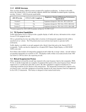
... for installing the Garmin GTX 23 Mode S Transponder. 1.2 Equipment Description The Garmin GTX 23 remote-mounted Mode S Transponder is a radio transmitter and receiver that it transmits a coded response of aircraft information without a request. It receives ground radar and TCAS interrogations at 1030 MHz, and it must use main software version 3.20 or later. This helps the air traffic controller confirm your position on radar frequencies. Elementary Surveillance provides a detailed transponder capability report and aircraft identification data (e.g. GTX 23 Installation Manual...
... for installing the Garmin GTX 23 Mode S Transponder. 1.2 Equipment Description The Garmin GTX 23 remote-mounted Mode S Transponder is a radio transmitter and receiver that it transmits a coded response of aircraft information without a request. It receives ground radar and TCAS interrogations at 1030 MHz, and it must use main software version 3.20 or later. This helps the air traffic controller confirm your position on radar frequencies. Elementary Surveillance provides a detailed transponder capability report and aircraft identification data (e.g. GTX 23 Installation Manual...
Installation Manual
Page 10
... information in the cockpit for the duration of the transmission. As shown in the table below to the other equipment on board that is suppressed by the GTX 23 transponder. Traffic display is designed to aircraft equipped with a Mode S data link such as the transponder. This feature is available to limit mutual interference. Page 1-2 Revision A GTX 23 Installation Manual 190-00906-01 The TIS ground sensor uses real time track...
... information in the cockpit for the duration of the transmission. As shown in the table below to the other equipment on board that is suppressed by the GTX 23 transponder. Traffic display is designed to aircraft equipped with a Mode S data link such as the transponder. This feature is available to limit mutual interference. Page 1-2 Revision A GTX 23 Installation Manual 190-00906-01 The TIS ground sensor uses real time track...
Installation Manual
Page 11
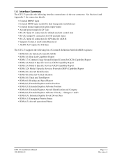
... C for connection details. • External IDENT input • External STBY input (useful for dual transponder installations) • External mutual suppression pulse input/output • Aircraft power input (14/28 Vdc) • RS-232 input #1 connection for altitude and unit control data • RS-232 output #1 connection for TIS and unit status • RS-232 input #2 connection for GPS data for ADS-B • Supports Comm-A and Comm-B protocol • ARINC 429 outputs for TIS data The GTX 23 supports the following interface connections via the rear connector. Subtypes 1 and...
... C for connection details. • External IDENT input • External STBY input (useful for dual transponder installations) • External mutual suppression pulse input/output • Aircraft power input (14/28 Vdc) • RS-232 input #1 connection for altitude and unit control data • RS-232 output #1 connection for TIS and unit status • RS-232 input #2 connection for GPS data for ADS-B • Supports Comm-A and Comm-B protocol • ARINC 429 outputs for TIS data The GTX 23 supports the following interface connections via the rear connector. Subtypes 1 and...

Installation Manual
Page 12
GTX 23 w/ES Unit Software Complex Electronic Hardware FCC Authorization Temperature Range Altitude Transmitter Frequency Transmitter Power Receiver Frequency Receiver Sensitivity Mode A Capability Mode C Capability Mode S Capability External Suppression Input External Suppression Output Audio Output Specification RTCA DO-160D, DO-181C, and EUROCAE/ED-73B RTCA DO-178B Level C RTCA/DO-254 Level C Emission Designator 12M0M1D -45°C to +70°C (continuous operation) 55,000 Feet 1090 MHz ±1 MHz 125 Watts minimum, 250...
GTX 23 w/ES Unit Software Complex Electronic Hardware FCC Authorization Temperature Range Altitude Transmitter Frequency Transmitter Power Receiver Frequency Receiver Sensitivity Mode A Capability Mode C Capability Mode S Capability External Suppression Input External Suppression Output Audio Output Specification RTCA DO-160D, DO-181C, and EUROCAE/ED-73B RTCA DO-178B Level C RTCA/DO-254 Level C Emission Designator 12M0M1D -45°C to +70°C (continuous operation) 55,000 Feet 1090 MHz ±1 MHz 125 Watts minimum, 250...

Installation Manual
Page 13
... if performed under 14 CFR Part 43 or the applicable airworthiness requirements. The GTX 23 owner accepts all responsibility for aircraft and ships. The GTX 23 installation must comply with current transmitter licensing requirements. To find out the specific details on whether a particular installation is required, make application for a license on -demand service to provide forms by Garmin could invalidate the license...
... if performed under 14 CFR Part 43 or the applicable airworthiness requirements. The GTX 23 owner accepts all responsibility for aircraft and ships. The GTX 23 installation must comply with current transmitter licensing requirements. To find out the specific details on whether a particular installation is required, make application for a license on -demand service to provide forms by Garmin could invalidate the license...
Installation Manual
Page 16
... for new Remote-Mount and Panel-Mount products; THIS WARRANTY GIVES YOU SPECIFIC LEGAL RIGHTS, WHICH MAY VARY FROM STATE TO STATE. To obtain warranty service, an original or copy of the sales receipt from the date of purchase for any transportation cost. Garmin International, Inc. 1200 East 151st Street Olathe, Kansas 66062, U.S.A. Such repairs or replacement will be free from...
... for new Remote-Mount and Panel-Mount products; THIS WARRANTY GIVES YOU SPECIFIC LEGAL RIGHTS, WHICH MAY VARY FROM STATE TO STATE. To obtain warranty service, an original or copy of the sales receipt from the date of purchase for any transportation cost. Garmin International, Inc. 1200 East 151st Street Olathe, Kansas 66062, U.S.A. Such repairs or replacement will be free from...

Installation Manual
Page 17
... part numbers: Item Catalog Part Number GTX 23 w/ES, Unit Only, (011-02803-02) 010-01014-02 GTX 23 w/ES and Install Kit, (011-02803-02) 010-01014-03 2.2.1 Equipment Available Each of FAA advisory circulars AC 43.13-1B and AC 43.13-2B, where applicable, may be used with the aircraft manufacturer's original design. Cable requirements and fabrication is detailed in this manual. • Hardware...
... part numbers: Item Catalog Part Number GTX 23 w/ES, Unit Only, (011-02803-02) 010-01014-02 GTX 23 w/ES and Install Kit, (011-02803-02) 010-01014-03 2.2.1 Equipment Available Each of FAA advisory circulars AC 43.13-1B and AC 43.13-2B, where applicable, may be used with the aircraft manufacturer's original design. Cable requirements and fabrication is detailed in this manual. • Hardware...

Installation Manual
Page 19
.... GTX 23 Installation Manual 190-00906-01 Page 2-3 Revision A One can determine the length of cable needed to connect the transponder to the antenna, and then use the table to the interconnect examples in Appendix C for the cabling and mating connectors. This loss specification includes connector loss; 2.4 Cabling and Wiring Refer to look up a recommended cable manufacturer and part number that routing of the wiring does not come in cabling and routing near sharp edges because aircraft...
.... GTX 23 Installation Manual 190-00906-01 Page 2-3 Revision A One can determine the length of cable needed to connect the transponder to the antenna, and then use the table to the interconnect examples in Appendix C for the cabling and mating connectors. This loss specification includes connector loss; 2.4 Cabling and Wiring Refer to look up a recommended cable manufacturer and part number that routing of the wiring does not come in cabling and routing near sharp edges because aircraft...

Installation Manual
Page 20
... aircraft to minimize radiated EMI and provide protection from being breached. • Avoid routing close to sharp edges to the airframe by a 4.3-pound (1.95 kg) GTX 23 unit, rack, and connectors (see Section 1.7.1 for weight information). After the cable assemblies are made and wiring installed to provide strain relief for maximizing the life of rack mounting structures and determining static load capability. Use cable...
... aircraft to minimize radiated EMI and provide protection from being breached. • Avoid routing close to sharp edges to the airframe by a 4.3-pound (1.95 kg) GTX 23 unit, rack, and connectors (see Section 1.7.1 for weight information). After the cable assemblies are made and wiring installed to provide strain relief for maximizing the life of rack mounting structures and determining static load capability. Use cable...

Installation Manual
Page 23
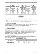
... through one 62-pin D-subminiature connector. The installer shall supply and fabricate all input and output signals. Section 4 defines the electrical characteristics of all cables. Table 3-1: Pin Contact Part Numbers Manufacturer Garmin P/N Military P/N AMP Positronic ITT Cannon 62 pin D-Subminiature connector (P2301) 18 AWG (Power Only) 20-24 AWG 336-0004400 336-00021-00 N/A M39029/58-360 N/A 204370-2 N/A MC8522D N/A 030-2042-000 GTX 23 Installation Manual 190-00906...
... through one 62-pin D-subminiature connector. The installer shall supply and fabricate all input and output signals. Section 4 defines the electrical characteristics of all cables. Table 3-1: Pin Contact Part Numbers Manufacturer Garmin P/N Military P/N AMP Positronic ITT Cannon 62 pin D-Subminiature connector (P2301) 18 AWG (Power Only) 20-24 AWG 336-0004400 336-00021-00 N/A M39029/58-360 N/A 204370-2 N/A MC8522D N/A 030-2042-000 GTX 23 Installation Manual 190-00906...
Installation Manual
Page 24
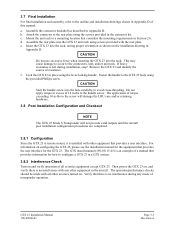
...: Table 3-3 Unit Power Loads GTX 23 Input GTX 23 Main Power 14 Vdc Typical Max. 1.6 A 3.1 A 28 Vdc Typical Max. 0.85 A 1.6 A Page 3-2 Revision A GTX 23 Installation Manual 190-00906-01 Make appropriate entries in the aircraft records. A new contact must be completed on each aircraft prior to the absence of gravity. 3.6 Electrical Load Analysis An electrical load analysis should be used when reassembling the connector. 3.4 Backshell Assembly The GTX 23 connector kit includes one Garmin backshell...
...: Table 3-3 Unit Power Loads GTX 23 Input GTX 23 Main Power 14 Vdc Typical Max. 1.6 A 3.1 A 28 Vdc Typical Max. 0.85 A 1.6 A Page 3-2 Revision A GTX 23 Installation Manual 190-00906-01 Make appropriate entries in the aircraft records. A new contact must be completed on each aircraft prior to the absence of gravity. 3.6 Electrical Load Analysis An electrical load analysis should be used when reassembling the connector. 3.4 Backshell Assembly The GTX 23 connector kit includes one Garmin backshell...
Installation Manual
Page 25
... provides a user interface. d. CAUTION Do not use excessive force when inserting the GTX 23 into the rack, noting proper orientation as described in -lbs to the screw will damage the LRU case and/or retaining hardware. 3.8 Post Installation Configuration and Checkout NOTE The GTX 23 Mode S Transponder will not provide valid outputs until the aircraft post installation configuration procedures are completed. 3.8.1 Configuration Since the GTX 23 is remote mount, it is...
... provides a user interface. d. CAUTION Do not use excessive force when inserting the GTX 23 into the rack, noting proper orientation as described in -lbs to the screw will damage the LRU case and/or retaining hardware. 3.8 Post Installation Configuration and Checkout NOTE The GTX 23 Mode S Transponder will not provide valid outputs until the aircraft post installation configuration procedures are completed. 3.8.1 Configuration Since the GTX 23 is remote mount, it is...

Installation Manual
Page 28
... A GTX 23 Installation Manual 190-00906-01 P2301 58 -- The power input pins accept 14/28 Vdc. Refer to activate). Connector P2301, continued Pin Pin Name I/O 36 NOT USED -- 37 ARINC 429 OUT 1 A Out 38 NOT USED -- 39 POWER GROUND -- 40 NOT USED -- 41 NOT USED -- 42 AIRCRAFT POWER 1 In 43 RS-232 GROUND -- 44 NOT USED -- 45 NOT USED In 46 TIS CONNECT SELECT* In 47 NOT USED -- 48 NOT USED -- 49 NOT USED -- 50...
... A GTX 23 Installation Manual 190-00906-01 P2301 58 -- The power input pins accept 14/28 Vdc. Refer to activate). Connector P2301, continued Pin Pin Name I/O 36 NOT USED -- 37 ARINC 429 OUT 1 A Out 38 NOT USED -- 39 POWER GROUND -- 40 NOT USED -- 41 NOT USED -- 42 AIRCRAFT POWER 1 In 43 RS-232 GROUND -- 44 NOT USED -- 45 NOT USED In 46 TIS CONNECT SELECT* In 47 NOT USED -- 48 NOT USED -- 49 NOT USED -- 50...

Installation Manual
Page 29
... 200 uA max for 18 seconds in Mode A replies. GTX 23 Installation Manual 190-00906-01 Page 4-3 Revision A Known incompatible DME units include the Bendix/King KN 62, KN 64 and KNS 80. When EXTERNAL STANDBY SELECT is not a momentary input. TIS CONNECT SELECT is a momentary input. When grounded, it toggles whether TIS is installed in the aircraft avionics system. These models have an output-only suppression...
... 200 uA max for 18 seconds in Mode A replies. GTX 23 Installation Manual 190-00906-01 Page 4-3 Revision A Known incompatible DME units include the Bendix/King KN 62, KN 64 and KNS 80. When EXTERNAL STANDBY SELECT is not a momentary input. TIS CONNECT SELECT is a momentary input. When grounded, it toggles whether TIS is installed in the aircraft avionics system. These models have an output-only suppression...

Installation Manual
Page 31
... equipment attached to an antenna or a 50 Ω, 5-Watt load (Figure 4-2). Instead of the system, it may be installed that the GTX 23 must be turned on a remote avionics shelf next to a 50 Ω, 5-Watt load when the unit transmits. GTX 23 50Ω 5 WATT Figure 4-2 GTX 23 Software Update Connections GTX 23 Installation Manual 190-00906-01 Page 4-5 Revision A The connector can be useful for software update connections. Also when wiring, consider that disconnects the...
... equipment attached to an antenna or a 50 Ω, 5-Watt load (Figure 4-2). Instead of the system, it may be installed that the GTX 23 must be turned on a remote avionics shelf next to a 50 Ω, 5-Watt load when the unit transmits. GTX 23 50Ω 5 WATT Figure 4-2 GTX 23 Software Update Connections GTX 23 Installation Manual 190-00906-01 Page 4-5 Revision A The connector can be useful for software update connections. Also when wiring, consider that disconnects the...

Installation Manual
Page 38
... AWG strands to the shield using an approved shield termination technique. Page B-4 Revision A GTX 23 Installation Manual 190-00906-01 3. Solder Sleeves with the thermochromic temperature indicator (S03-02-R-9035-100, S03-03-R-9035-100, S03-04-R-9035-100). Preferred Method: Slide a solder sleeve (Item 5) onto the prepared cable assembly (Item 4) and connect the Flat Braid (Item...
... AWG strands to the shield using an approved shield termination technique. Page B-4 Revision A GTX 23 Installation Manual 190-00906-01 3. Solder Sleeves with the thermochromic temperature indicator (S03-02-R-9035-100, S03-03-R-9035-100, S03-04-R-9035-100). Preferred Method: Slide a solder sleeve (Item 5) onto the prepared cable assembly (Item 4) and connect the Flat Braid (Item...

Installation Manual
Page 49
... BE CONFIGURED FOR THIS SETUP. THE GTX 23 REQUIRES THAT ARINC 429 OUTPUT #2 BE USED FOR TIS, BUT ANY UNUSED ARINC 429 INPUT ON THE GNS MAY BE USED. 5. THE SINGLE WIRE CONNECTED TO THE TIS CONNECT SELECT INPUT OF THE GTX 23 IS OPTIONAL. WHEN TIS IS USED ON A GNS, DO NOT CONNECT ANOTHER TRAFFIC SYSTEM TO THE SAME GNS SERIES UNIT. 6. THIS WIRE IS NECESSARY TO PUT TIS INTO AND BRING IT OUT OF STANDBY MODE. TIS Setup...
... BE CONFIGURED FOR THIS SETUP. THE GTX 23 REQUIRES THAT ARINC 429 OUTPUT #2 BE USED FOR TIS, BUT ANY UNUSED ARINC 429 INPUT ON THE GNS MAY BE USED. 5. THE SINGLE WIRE CONNECTED TO THE TIS CONNECT SELECT INPUT OF THE GTX 23 IS OPTIONAL. WHEN TIS IS USED ON A GNS, DO NOT CONNECT ANOTHER TRAFFIC SYSTEM TO THE SAME GNS SERIES UNIT. 6. THIS WIRE IS NECESSARY TO PUT TIS INTO AND BRING IT OUT OF STANDBY MODE. TIS Setup...


