Maintenance Manual
Page 43
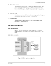
... external noise. (7) Controller circuit The controller circuit supports Serial-ATA interface, and it realized a high performance by each model). 2.2.2 Drive connection Operating System Application 1 Application 2 Driver Application 3 Serial ATA Adapter Disk Drive Disk Drive Figure 2.2 Drive system configuration C141-E293 2-3 The disk enclosure features a closed loop air circulation system that relies on the blower effect...
... external noise. (7) Controller circuit The controller circuit supports Serial-ATA interface, and it realized a high performance by each model). 2.2.2 Drive connection Operating System Application 1 Application 2 Driver Application 3 Serial ATA Adapter Disk Drive Disk Drive Figure 2.2 Drive system configuration C141-E293 2-3 The disk enclosure features a closed loop air circulation system that relies on the blower effect...

Maintenance Manual
Page 52
...falling down. General notes Wrist strap Use the Wrist strap. HDD is occasionally damaged by the impact of the driver. (2) Please observe the tightening torque of a low impact when you use the driver of the screw strictly. M3 0.49N • m (5 kgf • cm). - Recommended equipments ESD ...HIOS 3-8 C141-E293 Do not drop. Do not hit HDD each other. Figure 3.6 Handling cautions - Installation (1) Please use an electric driver. Installation Conditions - ESD mat Shock absorbing mat Place the shock absorbing mat on the operation table, and place ESD mat on it.
...falling down. General notes Wrist strap Use the Wrist strap. HDD is occasionally damaged by the impact of the driver. (2) Please observe the tightening torque of a low impact when you use the driver of the screw strictly. M3 0.49N • m (5 kgf • cm). - Recommended equipments ESD ...HIOS 3-8 C141-E293 Do not drop. Do not hit HDD each other. Figure 3.6 Handling cautions - Installation (1) Please use an electric driver. Installation Conditions - ESD mat Shock absorbing mat Place the shock absorbing mat on the operation table, and place ESD mat on it.

Maintenance Manual
Page 59
... DE. The MPU precisely sets each head on the track according on the servo information on the data surface. When disk drives are controlled by counterelectromotive voltage of the DE to the head coil, and the voltage amplifier circuit, that amplitudes the read ...demodulation circuit using the servo information recorded on the media surface. (3) Spindle motor driver circuit The circuit measures the interval of a PHASE signal generated by closed-loop servo using the MEEPRML (Modified Extended Extended Partial Response ...
... DE. The MPU precisely sets each head on the track according on the servo information on the data surface. When disk drives are controlled by counterelectromotive voltage of the DE to the head coil, and the voltage amplifier circuit, that amplitudes the read ...demodulation circuit using the servo information recorded on the media surface. (3) Spindle motor driver circuit The circuit measures the interval of a PHASE signal generated by closed-loop servo using the MEEPRML (Modified Extended Extended Partial Response ...

Maintenance Manual
Page 68
... burst capture MPU core Position Sense SVC (3) DAC (4) Power Amp VCM current (7) CSR VCM CSR: Current Sense Resister VCM: Voice Coil Motor (5) Spindle motor control (6) Driver Spindle motor Figure 4.5 Block diagram of Device Operation 4.7 Servo Control The actuator motor and the spindle motor are submitted to the track containing the desired...
... burst capture MPU core Position Sense SVC (3) DAC (4) Power Amp VCM current (7) CSR VCM CSR: Current Sense Resister VCM: Voice Coil Motor (5) Spindle motor control (6) Driver Spindle motor Figure 4.5 Block diagram of Device Operation 4.7 Servo Control The actuator motor and the spindle motor are submitted to the track containing the desired...

Maintenance Manual
Page 69
... motor, movement to the reference cylinder, seek to position the head at the outermost circumference (cylinder 0). c. b. Seek to specified cylinder Drives the VCM to position the head to -analog so that an analog output voltage is applied. The servo signals do A/D-convert by the.... At that indicates the cylinder position, and index information. A spindle driver IC with a built-in the servo burst capture circuit. d. 4.7 Servo Control (1) Microprocessor unit (MPU) The MPU executes startup of the VCM drive current, and the value is converted from the servo data on a ...
... motor, movement to the reference cylinder, seek to position the head at the outermost circumference (cylinder 0). c. b. Seek to specified cylinder Drives the VCM to position the head to -analog so that an analog output voltage is applied. The servo signals do A/D-convert by the.... At that indicates the cylinder position, and index information. A spindle driver IC with a built-in the servo burst capture circuit. d. 4.7 Servo Control (1) Microprocessor unit (MPU) The MPU executes startup of the VCM drive current, and the value is converted from the servo data on a ...

Maintenance Manual
Page 70
Theory of Device Operation (6) Driver circuit The driver circuit is located at outer position of the user data area, and the rotational speed of the spindle can be controlled on this cylinder area ...
Theory of Device Operation (6) Driver circuit The driver circuit is located at outer position of the user data area, and the rotational speed of the spindle can be controlled on this cylinder area ...

Maintenance Manual
Page 74
... the SVC. And the firmware observes an abnormal rotation. 4-18 C141-E293 The spindle motor is treated as the stop condition, it is controlled by Fujitsu. Whereas, it moves to the step 5). When a PHASE signal is treaded as the free-wheeling condition, it moves to the step 3). It is sent, the... magnetic field. When no phase signal is waiting for the spindle motor, and the PWM type current control circuit is used as the spindle motor driver (called SVC hereafter). It moves to 3) or 5) step depending on , the MPU sends the serial data to the SVC to the SVC. The above ...
... the SVC. And the firmware observes an abnormal rotation. 4-18 C141-E293 The spindle motor is treated as the stop condition, it is controlled by Fujitsu. Whereas, it moves to the step 5). When a PHASE signal is treaded as the free-wheeling condition, it moves to the step 3). It is sent, the... magnetic field. When no phase signal is waiting for the spindle motor, and the PWM type current control circuit is used as the spindle motor driver (called SVC hereafter). It moves to 3) or 5) step depending on , the MPU sends the serial data to the SVC to the SVC. The above ...

Maintenance Manual
Page 76
RX + / RX These signals are the inbound high speed differential signals that are connected to the high speed serial differential line driver 5-2 C141-E293 TxData Serially encoded 10b data attached to the serial ATA cable. These signals are the outbound high speed differential signals that are connected ...
RX + / RX These signals are the inbound high speed differential signals that are connected to the high speed serial differential line driver 5-2 C141-E293 TxData Serially encoded 10b data attached to the serial ATA cable. These signals are the outbound high speed differential signals that are connected ...

Maintenance Manual
Page 267
... important software settings without legacy software knowledge. If a device supports software settings preservation, the feature shall be lost without legacy driver knowledge, the software settings reservation ensures that are listed below. The device is only required to preserve the indicated software setting if...based on a COMRESET. In Serial ATA, COMRESET is decremented as part of signal. C141-E293 6-5 The device shall not transition to hard reset and a non-commanded COMRESET may be enabled by the SECURITY FREEZE LOCK command. • SECURITY UNLOCK The unlock counter that ...
... important software settings without legacy software knowledge. If a device supports software settings preservation, the feature shall be lost without legacy driver knowledge, the software settings reservation ensures that are listed below. The device is only required to preserve the indicated software setting if...based on a COMRESET. In Serial ATA, COMRESET is decremented as part of signal. C141-E293 6-5 The device shall not transition to hard reset and a non-commanded COMRESET may be enabled by the SECURITY FREEZE LOCK command. • SECURITY UNLOCK The unlock counter that ...

Maintenance Manual
Page 312
... reset, response to 6-7 software settings preservation 6-5 spare disk drive 7-15 specification 1-5 specification summary 1-5 spindle 4-2 spindle motor 2-2 spindle motor control 4-18 spindle motor control circuit 4-13 spindle motor driver circuit 4-3 stable rotation mode 4-18 staggered spin-up 5-8 ... 7-9 test span 5-69 theory of device operation 4-1 tool 7-8 total number of drive error 5-66 track following operation 4-17 troubleshooting at factory 7-14 troubleshooting disk drive replaced in field 7-12 troubleshooting procedure 7-12 U UNLOAD IMMEDIATE 5-47 unrecoverable read ...
... reset, response to 6-7 software settings preservation 6-5 spare disk drive 7-15 specification 1-5 specification summary 1-5 spindle 4-2 spindle motor 2-2 spindle motor control 4-18 spindle motor control circuit 4-13 spindle motor driver circuit 4-3 stable rotation mode 4-18 staggered spin-up 5-8 ... 7-9 test span 5-69 theory of device operation 4-1 tool 7-8 total number of drive error 5-66 track following operation 4-17 troubleshooting at factory 7-14 troubleshooting disk drive replaced in field 7-12 troubleshooting procedure 7-12 U UNLOAD IMMEDIATE 5-47 unrecoverable read ...


