Manual/User Guide
Page 9
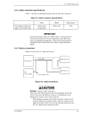
Host system ATA-cable Disk Drive #0 ATA-cable DC Power supply Power supply cable Disk Drive #1 Figure 3.8 Cable connections C141-E250 Damage: Interface cable connection Take note of the following precaution about plugging an interface cable (socket) into the interface connector of the disk drive and plugging the connector into a host receptacle: − When plugging together...
Host system ATA-cable Disk Drive #0 ATA-cable DC Power supply Power supply cable Disk Drive #1 Figure 3.8 Cable connections C141-E250 Damage: Interface cable connection Take note of the following precaution about plugging an interface cable (socket) into the interface connector of the disk drive and plugging the connector into a host receptacle: − When plugging together...
Manual/User Guide
Page 10
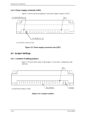
Figure 3.9 Power supply connector pins (CN1) 3.4 Jumper Settings 3.4.1 Location of setting jumpers Figure 3.10 shows the location of the power supply connector (CN1). Installation Conditions 3.3.4 Power supply connector (CN1) Figure 3.9 shows the pin assignment of the jumpers to select drive configuration and functions. Figure 3.10 Jumper location 3-10 C141-E250
Figure 3.9 Power supply connector pins (CN1) 3.4 Jumper Settings 3.4.1 Location of setting jumpers Figure 3.10 shows the location of the power supply connector (CN1). Installation Conditions 3.3.4 Power supply connector (CN1) Figure 3.9 shows the pin assignment of the jumpers to select drive configuration and functions. Figure 3.10 Jumper location 3-10 C141-E250
Manual/User Guide
Page 13
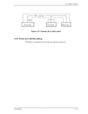
3.4 Jumper Settings drive Figure 3.15 Example (2) of cable select drive 3.4.5 Power up in standby setting When pin C is grounded, the drive does not spin up at power on. C141-E250 3-13
3.4 Jumper Settings drive Figure 3.15 Example (2) of cable select drive 3.4.5 Power up in standby setting When pin C is grounded, the drive does not spin up at power on. C141-E250 3-13