Manual/User Guide
Page 1
CHAPTER 3 Installation Conditions 3.1 Dimensions 3.2 Mounting 3.3 Cable Connections 3.4 Jumper Settings This chapter gives the external dimensions, installation conditions, surface temperature conditions, cable connections, and switch settings of the hard disk drives. C141-E144 C141-E250 3-1 For information about handling this hard disk drive and the system installation procedure, refer to the following Integration Guide.
CHAPTER 3 Installation Conditions 3.1 Dimensions 3.2 Mounting 3.3 Cable Connections 3.4 Jumper Settings This chapter gives the external dimensions, installation conditions, surface temperature conditions, cable connections, and switch settings of the hard disk drives. C141-E144 C141-E250 3-1 For information about handling this hard disk drive and the system installation procedure, refer to the following Integration Guide.
Manual/User Guide
Page 6
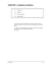
... not touch the printed circuit board, but hold it too hard, the cover and the spindle motor contact, which may cause damage to the disk drive. Mounting screw hole Cable connection Mounting screw hole Figure 3.5 Service area Data corruption: Avoid mounting the disk drive near strong magnetic sources such as loud speakers. Static: When...
... not touch the printed circuit board, but hold it too hard, the cover and the spindle motor contact, which may cause damage to the disk drive. Mounting screw hole Cable connection Mounting screw hole Figure 3.5 Service area Data corruption: Avoid mounting the disk drive near strong magnetic sources such as loud speakers. Static: When...
Manual/User Guide
Page 8
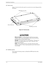
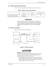
Connector, setting pins PCA Figure 3.7 Connector locations 3-8 C141-E250 Installation Conditions 3.3 Cable Connections 3.3.1 Device connector The disk drive has the connectors and terminals listed below for connecting external devices. Figure 3.7 shows the locations of these connectors and terminals.
Connector, setting pins PCA Figure 3.7 Connector locations 3-8 C141-E250 Installation Conditions 3.3 Cable Connections 3.3.1 Device connector The disk drive has the connectors and terminals listed below for connecting external devices. Figure 3.7 shows the locations of these connectors and terminals.
Manual/User Guide
Page 9
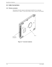
... may cause crosstalk between signal lines. Host system ATA-cable Disk Drive #0 ATA-cable DC Power supply Power supply cable Disk Drive #1 Figure 3.8 Cable connections C141-E250 Damage: Interface cable connection Take note of the following precaution about plugging an interface cable (socket) into the interface connector of the disk drive and plugging the connector into a host receptacle: −...
... may cause crosstalk between signal lines. Host system ATA-cable Disk Drive #0 ATA-cable DC Power supply Power supply cable Disk Drive #1 Figure 3.8 Cable connections C141-E250 Damage: Interface cable connection Take note of the following precaution about plugging an interface cable (socket) into the interface connector of the disk drive and plugging the connector into a host receptacle: −...
Manual/User Guide
Page 12
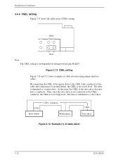
...3.14 and 3.15 show examples of the slave drive does not have a conductor. At this time, the CSEL of cable selection using unique interface cables. The drive is identified as a slave drive. The drive is identified as a master drive. Thus, since the slave drive is not connected to the CSEL conductor, the ... depended on setting between pins Band D. Open 1 CA 2 DB Short Note: The CSEL setting is set to high level. drive drive Figure 3.14 Example (1) of the cable and connecting it to ground further, the CSEL is set to low level. By connecting the CSEL of the master...
...3.14 and 3.15 show examples of the slave drive does not have a conductor. At this time, the CSEL of cable selection using unique interface cables. The drive is identified as a slave drive. The drive is identified as a master drive. Thus, since the slave drive is not connected to the CSEL conductor, the ... depended on setting between pins Band D. Open 1 CA 2 DB Short Note: The CSEL setting is set to high level. drive drive Figure 3.14 Example (1) of the cable and connecting it to ground further, the CSEL is set to low level. By connecting the CSEL of the master...
Manual/User Guide
Page 13
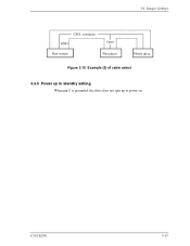
C141-E250 3-13 3.4 Jumper Settings drive Figure 3.15 Example (2) of cable select drive 3.4.5 Power up in standby setting When pin C is grounded, the drive does not spin up at power on.
C141-E250 3-13 3.4 Jumper Settings drive Figure 3.15 Example (2) of cable select drive 3.4.5 Power up in standby setting When pin C is grounded, the drive does not spin up at power on.