Manual/User Guide
Page 9
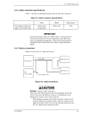
... connection Take note of the following precaution about plugging an interface cable (socket) into the interface connector of the disk drive and plugging the connector into a host receptacle: − When plugging together the disk drive interface connector and the host receptacle or interface cable connector (socket), do not apply more than 10 kgf of force in...
... connection Take note of the following precaution about plugging an interface cable (socket) into the interface connector of the disk drive and plugging the connector into a host receptacle: − When plugging together the disk drive interface connector and the host receptacle or interface cable connector (socket), do not apply more than 10 kgf of force in...
Manual/User Guide
Page 12
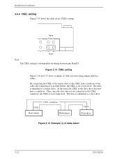
...of cable select 3-12 C141-E250 The drive is not depended on setting between pins Band D. Thus, since the slave drive is not connected to the CSEL conductor, the CSEL is set to high level. drive drive Figure 3.14 Example (1) of the slave drive does not have a conductor. Installation Conditions...of the cable and connecting it to ground further, the CSEL is identified as a master drive. By connecting the CSEL of the master drive to the CSEL Line (conducer) of cable selection using unique interface cables. Open 1 CA 2 DB Short Note: The CSEL setting is identified as a ...
...of cable select 3-12 C141-E250 The drive is not depended on setting between pins Band D. Thus, since the slave drive is not connected to the CSEL conductor, the CSEL is set to high level. drive drive Figure 3.14 Example (1) of the slave drive does not have a conductor. Installation Conditions...of the cable and connecting it to ground further, the CSEL is identified as a master drive. By connecting the CSEL of the master drive to the CSEL Line (conducer) of cable selection using unique interface cables. Open 1 CA 2 DB Short Note: The CSEL setting is identified as a ...
