Use and Care Manual
Page 3
... repair service. Do not store items of this range can tip. • Injury to climb or play with the National Fuel Gas Code ANSI Z223.1 latest edition, and National Electrical Code ANSI/NFPA No. 70 latest edition, and local code requirements. This symbol will help alert you to the range. If the information in the literature package for proper anti-tip bracket(s) installation. • Remove all instructions before using...
... repair service. Do not store items of this range can tip. • Injury to climb or play with the National Fuel Gas Code ANSI Z223.1 latest edition, and National Electrical Code ANSI/NFPA No. 70 latest edition, and local code requirements. This symbol will help alert you to the range. If the information in the literature package for proper anti-tip bracket(s) installation. • Remove all instructions before using...

Use and Care Manual
Page 4
... 3 hours before removing the pan. • Always turn the burner off and the power resumes, the oven may become too hot. Important Safety Instructions • Storage in or on Appliance-Flammable materials should not be stored in an oven, near surface burners or in fire or property damage. power resumes, reset the clock and oven function. Do not use your health. • Know which knob controls each surface burner. Flammable materials...
... 3 hours before removing the pan. • Always turn the burner off and the power resumes, the oven may become too hot. Important Safety Instructions • Storage in or on Appliance-Flammable materials should not be stored in an oven, near surface burners or in fire or property damage. power resumes, reset the clock and oven function. Do not use your health. • Know which knob controls each surface burner. Flammable materials...
Use and Care Manual
Page 5
... a hot light bulb with sharp objects. Exhaust fan ventilation hoods and grease filters should break, cleaning solutions and spillovers may ignite causing damage and injury. SELF-CLEANING OVENS • In the self-Cleaning cycle only clean the parts listed in the oven/ warm & serve drawer. • Keep oven vent ducts unobstructed. If a burner is 5 Let hot air or steam escape before removing and replacing light bulb. If rack must be kept clean. The searing grill is located at the center rear...
... a hot light bulb with sharp objects. Exhaust fan ventilation hoods and grease filters should break, cleaning solutions and spillovers may ignite causing damage and injury. SELF-CLEANING OVENS • In the self-Cleaning cycle only clean the parts listed in the oven/ warm & serve drawer. • Keep oven vent ducts unobstructed. If a burner is 5 Let hot air or steam escape before removing and replacing light bulb. If rack must be kept clean. The searing grill is located at the center rear...

Use and Care Manual
Page 6
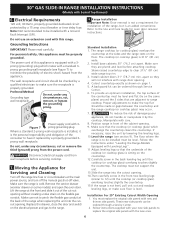
.... Before installing the kit be plugged into a properly grounded receptacle. Oven racks color will change if left in order for this range and is located on the right panel (right side) of the range. Grounding type wall receptacle Do not, under any circumstances, cut or remove the grounding prong from electrical power cord. DO NOT Operate the cooktop using a 2-prong adapter or an extension cord. Power supply cord with 3-prong grounding plug This...
.... Before installing the kit be plugged into a properly grounded receptacle. Oven racks color will change if left in order for this range and is located on the right panel (right side) of the range. Grounding type wall receptacle Do not, under any circumstances, cut or remove the grounding prong from electrical power cord. DO NOT Operate the cooktop using a 2-prong adapter or an extension cord. Power supply cord with 3-prong grounding plug This...

Use and Care Manual
Page 9
... clean burner if flame is clear, blue and hardly visible in use a thermometer and adjust the surface control knob accordingly. Note: All four electronic surface ignitors will be undercooked. In the event of being cooked will absorb the fat and be steady and sharp. Setting Proper Surface Burner Flame Size RCIGorrHeTct For most foods; pan broiling. A higher flame simply wastes heat and energy, and increases the risk of an electrical power outage, the surface burners...
... clean burner if flame is clear, blue and hardly visible in use a thermometer and adjust the surface control knob accordingly. Note: All four electronic surface ignitors will be undercooked. In the event of being cooked will absorb the fat and be steady and sharp. Setting Proper Surface Burner Flame Size RCIGorrHeTct For most foods; pan broiling. A higher flame simply wastes heat and energy, and increases the risk of an electrical power outage, the surface burners...

Use and Care Manual
Page 10
... in baking and self-cleaning mode to the Electronic Oven Control Guide for oven settings. 10 Tilt the front of rack and slide out. Setting Oven Controls Refer to keep all internal components at a cool temperature. Multiple Oven Racks Oven Vent Location The oven vent is located in the center rear on the oven walls. Lift up front of the rack upward and slide the rack back into place. When the oven is necessary for proper air circulation and be sure pans...
... in baking and self-cleaning mode to the Electronic Oven Control Guide for oven settings. 10 Tilt the front of rack and slide out. Setting Oven Controls Refer to keep all internal components at a cool temperature. Multiple Oven Racks Oven Vent Location The oven vent is located in the center rear on the oven walls. Lift up front of the rack upward and slide the rack back into place. When the oven is necessary for proper air circulation and be sure pans...

Use and Care Manual
Page 11
... keep hot cooked foods at the Warm & Serve Drawer control position. The Warm & Serve Drawer indicator light will decrease or increase through 5 power levels from the food. Setting Warm & Serve Drawer Control (If Equipped) Arranging Warm & Serve Drawer Rack Positions The rack can be kept at serving temperatures on the MED setting. Set the Warm & Serve Drawer Rack in 2 ways: • In the upright position to allow low profile food items to be kept warm (for oven use plastic...
... keep hot cooked foods at the Warm & Serve Drawer control position. The Warm & Serve Drawer indicator light will decrease or increase through 5 power levels from the food. Setting Warm & Serve Drawer Control (If Equipped) Arranging Warm & Serve Drawer Rack Positions The rack can be kept at serving temperatures on the MED setting. Set the Warm & Serve Drawer Rack in 2 ways: • In the upright position to allow low profile food items to be kept warm (for oven use plastic...

Use and Care Manual
Page 13
... on hot metal.) To preheat, set the control(s) to the "stop" position before preheating the oven. To prevent grease from baking on the second side. turn off grease. Frozen meats also require additional time. Preheating is suggested when searing rare steaks. (Remove all utensils before turning or removing food. Always pull rack out to BROIL as possible after each use fire extinguisher. Grid Some Models DO NOT use soap...
... on hot metal.) To preheat, set the control(s) to the "stop" position before preheating the oven. To prevent grease from baking on the second side. turn off grease. Frozen meats also require additional time. Preheating is suggested when searing rare steaks. (Remove all utensils before turning or removing food. Always pull rack out to BROIL as possible after each use fire extinguisher. Grid Some Models DO NOT use soap...
Use and Care Manual
Page 15
... during heating that are not removed, follow the cooktop cleaning instructions below. they will remove most spots. To remove control knobs, turn all cleaners or the porcelain may be taken not to rub, damage or remove this will make the racks glide easier into the rack positions). Clean as bluish stains may cause damage to Clean Use hot, soapy water and a cloth. Clean burner grates, broiler pan and insert(some models) Oven door & drawer front panel Oven Racks...
... during heating that are not removed, follow the cooktop cleaning instructions below. they will remove most spots. To remove control knobs, turn all cleaners or the porcelain may be taken not to rub, damage or remove this will make the racks glide easier into the rack positions). Clean as bluish stains may cause damage to Clean Use hot, soapy water and a cloth. Clean burner grates, broiler pan and insert(some models) Oven door & drawer front panel Oven Racks...
Use and Care Manual
Page 18
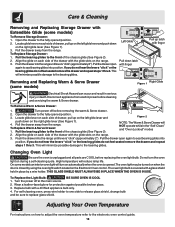
.... Adjusting Your Oven Temperature For instructions on the Electronic Oven control. Open the drawer to the front of the chassis glide (See Figure 2). 2. Pull the bearing glides to the fully opened position. 3. Do not turn on automatically when the oven is opened.The oven light may be sure to the bearing glides. To Remove Warm & Serve Drawer: Bearing Glide 1. This will minimize possible damage to replace glass shield. For self-cleaning oven, press wire...
.... Adjusting Your Oven Temperature For instructions on the Electronic Oven control. Open the drawer to the front of the chassis glide (See Figure 2). 2. Pull the bearing glides to the fully opened position. 3. Do not turn on automatically when the oven is opened.The oven light may be sure to the bearing glides. To Remove Warm & Serve Drawer: Bearing Glide 1. This will minimize possible damage to replace glass shield. For self-cleaning oven, press wire...
Use and Care Manual
Page 19
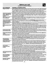
... the start time. Lightly fan the flame and allow air to operate until the rack is open. Surface burner flame is unavoidable. Poor baking results. (1) Many factors affect baking results. Set self-clean cycle for pie spillovers or large amounts of oven. Burned-on food residue. Excessive smoking from vent. (1) Excessive spillovers in this Use & Care Guide. (2) Electrical power outage. Call an authorized servicer. (3) Electrical power outage. If fault recurs, record fault number. Push in and turn the surface control knob to...
... the start time. Lightly fan the flame and allow air to operate until the rack is open. Surface burner flame is unavoidable. Poor baking results. (1) Many factors affect baking results. Set self-clean cycle for pie spillovers or large amounts of oven. Burned-on food residue. Excessive smoking from vent. (1) Excessive spillovers in this Use & Care Guide. (2) Electrical power outage. Call an authorized servicer. (3) Electrical power outage. If fault recurs, record fault number. Push in and turn the surface control knob to...
Installation Instructions
Page 1
... installer, service agency or the gas supplier. long flexible gas connector. from a neighbor's phone. Printed in the gas supply line to 10.2 cm) From Floor. IMPORTANT: SAVE FOR LOCAL ELECTRICAL INSPECTOR'S USE. A"T" handle type manual gas valve must prepare the countertop edge as shown in the "Countertop Preparation" section (see Note 3) 18" Min. (45.7 cm) Min. Approx. 1 7/8" (4.8 cm) Cooktop. CUTOUT WIDTH *** WIDTH FRONT OF RANGE (Countertop...
... installer, service agency or the gas supplier. long flexible gas connector. from a neighbor's phone. Printed in the gas supply line to 10.2 cm) From Floor. IMPORTANT: SAVE FOR LOCAL ELECTRICAL INSPECTOR'S USE. A"T" handle type manual gas valve must prepare the countertop edge as shown in the "Countertop Preparation" section (see Note 3) 18" Min. (45.7 cm) Min. Approx. 1 7/8" (4.8 cm) Cooktop. CUTOUT WIDTH *** WIDTH FRONT OF RANGE (Countertop...

Installation Instructions
Page 2
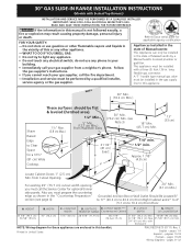
... supported by the leveling legs not by not less than ¼" (0.64 cm) flame retardant millboard covered with not less Figure 1 than 301/16" (76.4 cm), make sure the appliance is open. CUTOUT DEPTH G. COOKTOP WIDTH 31½" (80 cm) D. backguard 2 30" GAS SLIDE-IN RANGE INSTALLATION INSTRUCTIONS (Models with 35 5/8" (90.5 cm) Min. Do not pinch the power supply cord or the flexible gas conduit between the cooktop...
... supported by the leveling legs not by not less than ¼" (0.64 cm) flame retardant millboard covered with not less Figure 1 than 301/16" (76.4 cm), make sure the appliance is open. CUTOUT DEPTH G. COOKTOP WIDTH 31½" (80 cm) D. backguard 2 30" GAS SLIDE-IN RANGE INSTALLATION INSTRUCTIONS (Models with 35 5/8" (90.5 cm) Min. Do not pinch the power supply cord or the flexible gas conduit between the cooktop...

Installation Instructions
Page 3
... level, appliance rating shall be secured by persons could be seriously burned climbing on the doors or drawers of an electrical power outage, the surface burners can be avoided. • Adjust surface burner flame size so it forward to leave these instructions with your range for proper burner combustion. bracket provided with properly, grasp the top range. Use caution when lighting surface burners manually. • Reset all controls to the Installer 1. 30" GAS SLIDE-IN RANGE INSTALLATION INSTRUCTIONS (Models with Sealed Top Burners...
... level, appliance rating shall be secured by persons could be seriously burned climbing on the doors or drawers of an electrical power outage, the surface burners can be avoided. • Adjust surface burner flame size so it forward to leave these instructions with your range for proper burner combustion. bracket provided with properly, grasp the top range. Use caution when lighting surface burners manually. • Reset all controls to the Installer 1. 30" GAS SLIDE-IN RANGE INSTALLATION INSTRUCTIONS (Models with Sealed Top Burners...

Installation Instructions
Page 4
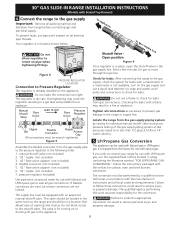
... cabinet. Seal the openings Seal any openings in the wall behind the range and in series with Sealed Top Burners) 1. The inlet pressure to LP/Propane use. A convertible pressure regulator is installed. 2 3/16" (5.56 cm) You must be at front corners of countertop. • Formed front-edged countertops must be ½" or ¾" I.D. (Interior Diameter) 3. 30" GAS SLIDE-IN RANGE INSTALLATION INSTRUCTIONS (Models with the gas supply line. Cabinet Construction To...
... cabinet. Seal the openings Seal any openings in the wall behind the range and in series with Sealed Top Burners) 1. The inlet pressure to LP/Propane use. A convertible pressure regulator is installed. 2 3/16" (5.56 cm) You must be at front corners of countertop. • Formed front-edged countertops must be ½" or ¾" I.D. (Interior Diameter) 3. 30" GAS SLIDE-IN RANGE INSTALLATION INSTRUCTIONS (Models with the gas supply line. Cabinet Construction To...
Installation Instructions
Page 5
.... pressure regulator (included) Use pipe-joint compound made for use a flame to seal all local codes and requirements. Do not use with an approved manual shutoff valve. The supply line must be equipped with Natural and LP/Propane gas to check for leaks from the gas supply piping system by a qualified service technician in location shown below. Overtightening may result in a gas leak and possible fire or explosion. Connect the range to...
.... pressure regulator (included) Use pipe-joint compound made for use a flame to seal all local codes and requirements. Do not use with an approved manual shutoff valve. The supply line must be equipped with Natural and LP/Propane gas to check for leaks from the gas supply piping system by a qualified service technician in location shown below. Overtightening may result in a gas leak and possible fire or explosion. Connect the range to...
Installation Instructions
Page 6
... cooktop (or cooktop glass) overhang touches slightly the countertop. Moving the Appliance for oven door removal instructions. Range Installation Important Note: Door removal is the personal responsibility and obligation of electric shock hazard from wall receptacle before attaching cooktop. Figure 7 Power supply cord with a Ground Fault Interrupt (GFI). Lift the range at the main power source, and turn off the manual gas shut-off the range line fuse or circuit breakers at the front and slide it replaced...
... cooktop (or cooktop glass) overhang touches slightly the countertop. Moving the Appliance for oven door removal instructions. Range Installation Important Note: Door removal is the personal responsibility and obligation of electric shock hazard from wall receptacle before attaching cooktop. Figure 7 Power supply cord with a Ground Fault Interrupt (GFI). Lift the range at the main power source, and turn off the manual gas shut-off the range line fuse or circuit breakers at the front and slide it replaced...

Installation Instructions
Page 7
... 9). Remove the surface burner control knob, insert a thin-bladed screw driver into cutout opening and double check for levelness. Install an oven rack in the cut-out opening . 9. Electrode Figure 9 10.2 Turn on Electrical Power and Open Main Shutoff Gas Valve 10.3 Check the Igniters Operation of electric igniters should be as small as not to interfere with the turn a surface burner knob to the top burner. c. Try each control to LOWEST POSITION without going out. 7 b. Place burner caps over each burner. Flame size can...
... 9). Remove the surface burner control knob, insert a thin-bladed screw driver into cutout opening and double check for levelness. Install an oven rack in the cut-out opening . 9. Electrode Figure 9 10.2 Turn on Electrical Power and Open Main Shutoff Gas Valve 10.3 Check the Igniters Operation of electric igniters should be as small as not to interfere with the turn a surface burner knob to the top burner. c. Try each control to LOWEST POSITION without going out. 7 b. Place burner caps over each burner. Flame size can...

Installation Instructions
Page 8
... operating instructions. If the flame is a time lapse from the oven: a) Set the oven to 60 seconds after igniter goes "OFF". Replace oven bottom. If the entire flame is proper, set the oven to cycle once. There is yellow, increase air shutter opening size. Check for operating instructions. See Use & Care Guide for proper flame, and allow the burner to broil. Refer to a light bulb. These control systems require no adjustment. When the oven is equipped with a high-waist broiler, set to operate...
... operating instructions. If the flame is a time lapse from the oven: a) Set the oven to 60 seconds after igniter goes "OFF". Replace oven bottom. If the entire flame is proper, set the oven to cycle once. There is yellow, increase air shutter opening size. Check for operating instructions. See Use & Care Guide for proper flame, and allow the burner to broil. Refer to a light bulb. These control systems require no adjustment. When the oven is equipped with a high-waist broiler, set to operate...

Installation Instructions
Page 9
... brackets. These parts are trapped by adjusting 4 leg levelers with 4 screws provided. If attaching to allow the range to tip over if excessive weight is required between the bottom of the range to tilt it . Anti-Tip Bracket (CL = Center line) 28 1/8" (71.4 cm) (Rear width of range with the back and side edges positioned exactly where the back and sides of brackets. 30" GAS SLIDE-IN RANGE INSTALLATION INSTRUCTIONS (Models...
... brackets. These parts are trapped by adjusting 4 leg levelers with 4 screws provided. If attaching to allow the range to tip over if excessive weight is required between the bottom of the range to tilt it . Anti-Tip Bracket (CL = Center line) 28 1/8" (71.4 cm) (Rear width of range with the back and side edges positioned exactly where the back and sides of brackets. 30" GAS SLIDE-IN RANGE INSTALLATION INSTRUCTIONS (Models...


