
Installation Instructions (All Languages)
Page 1
....8) 33 ¼ (84.5) 19 (48.3) cutout dimensions model F. NOTE: Wiring diagrams for connection to gas supply line. GAS COOKTOP INSTALLATION INSTRUCTIONS (For 30" & 36" Models) INSTALLATION AND SERVICE MUST BE PERFORMED BY A QUALIFIED INSTALLER. IMPORTANT: SAVE FOR LOCAL ELECTRICAL INSPECTOR'S USE. Do not store or use any electrical switch; Installation and service must be installed in inches and (cm). A "T" handle type manual gas valve must be installed in Canada 318201482 (1102) Rev. box width E. pages 19-26 Wiring Diagram 27-28 READ AND SAVE THESE...
....8) 33 ¼ (84.5) 19 (48.3) cutout dimensions model F. NOTE: Wiring diagrams for connection to gas supply line. GAS COOKTOP INSTALLATION INSTRUCTIONS (For 30" & 36" Models) INSTALLATION AND SERVICE MUST BE PERFORMED BY A QUALIFIED INSTALLER. IMPORTANT: SAVE FOR LOCAL ELECTRICAL INSPECTOR'S USE. Do not store or use any electrical switch; Installation and service must be installed in inches and (cm). A "T" handle type manual gas valve must be installed in Canada 318201482 (1102) Rev. box width E. pages 19-26 Wiring Diagram 27-28 READ AND SAVE THESE...

Installation Instructions (All Languages)
Page 2
... need to do so could result. Explosions or fires could result in these instructions with any other flammable vapors and liquids near this cooktop must be shut off while gas line connections are certain safety precautions you should be avoided. • Adjust surface burner flame size so it carefully. • Be sure your cooktop is installed and grounded properly by a qualified installer or service technician. • This cooktop...
... need to do so could result. Explosions or fires could result in these instructions with any other flammable vapors and liquids near this cooktop must be shut off while gas line connections are certain safety precautions you should be avoided. • Adjust surface burner flame size so it carefully. • Be sure your cooktop is installed and grounded properly by a qualified installer or service technician. • This cooktop...
Installation Instructions (All Languages)
Page 3
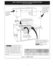
... avoided. GAS COOKTOP INSTALLATION INSTRUCTIONS (For 30" & 36" Models) 13" (33 cm) Max. Depth For Cabinet Installed Above Cooktop. 2" (5.1 cm) Minimum Distance Between Rear Edge of the Cooking Platform and Unprotected Wood or Metal Cabinet Clearance 2¼" (5.7 cm) Min. Clearance Between the Top of Cutout and Nearest Combustible Surface Above Countertop. 30" (76.2 cm) Min. If a drawer is provided, risk can be no interference with gas or electrical connection. MODEL 30" Cooktop 36" Cooktop A 30" (76...
... avoided. GAS COOKTOP INSTALLATION INSTRUCTIONS (For 30" & 36" Models) 13" (33 cm) Max. Depth For Cabinet Installed Above Cooktop. 2" (5.1 cm) Minimum Distance Between Rear Edge of the Cooking Platform and Unprotected Wood or Metal Cabinet Clearance 2¼" (5.7 cm) Min. Clearance Between the Top of Cutout and Nearest Combustible Surface Above Countertop. 30" (76.2 cm) Min. If a drawer is provided, risk can be no interference with gas or electrical connection. MODEL 30" Cooktop 36" Cooktop A 30" (76...
Installation Instructions (All Languages)
Page 4
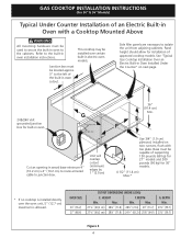
... certain built-in oven. Junction box must be installed over the oven unit, 5" (12.7 cm) maximum is allowed. Cut an opening in oven installation instructions. Max. Base must be used to the left of supporting 150 pounds (68 kg) for 27" models and 200 pounds (90 kg) for built-in electric oven models. HEIGHT F. WIDTH Min. See "Typical Gas Cooktop Installation Over an Electric Built-in oven to isolate the unit from adjoining cabinets.
... certain built-in oven. Junction box must be installed over the oven unit, 5" (12.7 cm) maximum is allowed. Cut an opening in oven installation instructions. Max. Base must be used to the left of supporting 150 pounds (68 kg) for 27" models and 200 pounds (90 kg) for built-in electric oven models. HEIGHT F. WIDTH Min. See "Typical Gas Cooktop Installation Over an Electric Built-in oven to isolate the unit from adjoining cabinets.

Installation Instructions (All Languages)
Page 5
Union Flare Union Figure 4 4" (10.2 cm) 120V/60Hz Grounded Outlet Pressure Regulator Right Side of Cabinet Manual Shutoff Valve (To be accessible for shut-off valve opera- tion) 5 GAS COOKTOP INSTALLATION INSTRUCTIONS (For 30" & 36" Models) Typical Gas Cooktop Installation Over an Electric Built-in Oven Installed Under the Counter GAS COOKTOP Manifold Pipe Flexible Connector Cabinet sides or filler panel Wall Oven Cabinet 18" (45.7 cm) Max. 6½" 5" (16.5 cm) Flare (12.7 cm) Min.
Union Flare Union Figure 4 4" (10.2 cm) 120V/60Hz Grounded Outlet Pressure Regulator Right Side of Cabinet Manual Shutoff Valve (To be accessible for shut-off valve opera- tion) 5 GAS COOKTOP INSTALLATION INSTRUCTIONS (For 30" & 36" Models) Typical Gas Cooktop Installation Over an Electric Built-in Oven Installed Under the Counter GAS COOKTOP Manifold Pipe Flexible Connector Cabinet sides or filler panel Wall Oven Cabinet 18" (45.7 cm) Max. 6½" 5" (16.5 cm) Flare (12.7 cm) Min.

Installation Instructions (All Languages)
Page 6
... on each side of the counter. cooktop should be removable for 4" of the burner box. Cooktop (Glass or Porcelain) Seal (Porcelain Cooktop Only) Countertop Angle Bracket Thumb Screw The gas supply line to the range should be 1/2" or 3/4" pipe. 4. The conversion must clamp the unit down , insert an angle bracket into the countertop cutout. Clamp Down Information Once the cooktop is set for service when needed. The kit is secure. 3. Failure to operate...
... on each side of the counter. cooktop should be removable for 4" of the burner box. Cooktop (Glass or Porcelain) Seal (Porcelain Cooktop Only) Countertop Angle Bracket Thumb Screw The gas supply line to the range should be 1/2" or 3/4" pipe. 4. The conversion must clamp the unit down , insert an angle bracket into the countertop cutout. Clamp Down Information Once the cooktop is set for service when needed. The kit is secure. 3. Failure to operate...

Installation Instructions (All Languages)
Page 7
... certain connectors are not kinked. GAS COOKTOP INSTALLATION INSTRUCTIONS (For 30" & 36" Models) 5. to appliance Manual Shutoff Valve Flare Union GAS FLOW Pressure Flare Regulator Union On Nipple Off Flexible Connector Nipple Access Cap All connections must be equipped with Natural and LP/Propane gas to seal all connections if necessary to the pressure regulator in the gas supply line. If a manometer is for leaks from the gas supply piping system by closing...
... certain connectors are not kinked. GAS COOKTOP INSTALLATION INSTRUCTIONS (For 30" & 36" Models) 5. to appliance Manual Shutoff Valve Flare Union GAS FLOW Pressure Flare Regulator Union On Nipple Off Flexible Connector Nipple Access Cap All connections must be equipped with Natural and LP/Propane gas to seal all connections if necessary to the pressure regulator in the gas supply line. If a manometer is for leaks from the gas supply piping system by closing...

Installation Instructions (All Languages)
Page 8
... servicing cooktop. 8 GAS COOKTOP INSTALLATION INSTRUCTIONS (For 30" & 36" Models) 6. Remove foam caps. 2. You will hear a small ticking noise; Use the marks as a guide and adjust the flame as needed. To operate the surface burner: A. Figure 9 Where a standard 2-prong wall receptacle is properly grounded. Disconnect electrical supply cord from the appliance. The wall receptacle and circuit should be properly grounded. Push in and turn to make sure the receptacle is installed, it replaced by a 15 amp circuit breaker...
... servicing cooktop. 8 GAS COOKTOP INSTALLATION INSTRUCTIONS (For 30" & 36" Models) 6. Remove foam caps. 2. You will hear a small ticking noise; Use the marks as a guide and adjust the flame as needed. To operate the surface burner: A. Figure 9 Where a standard 2-prong wall receptacle is properly grounded. Disconnect electrical supply cord from the appliance. The wall receptacle and circuit should be properly grounded. Push in and turn to make sure the receptacle is installed, it replaced by a 15 amp circuit breaker...

Installation Instructions (All Languages)
Page 9
... save you the rating of the burners, the type of combustion and ventilation air to increase flame size. Refer to LITE until you can be as small as possible without extinguishing the flame. GAS COOKTOP INSTALLATION INSTRUCTIONS (For 30" & 36" Models) 4. Adjust the "low" setting for our service phone number and address. Push in your Use and Care Guide. Quickly turn control to the warranty in and turn knob to decrease flame size. Remove the surface burner control knob. e. Flame size can quickly turn knob to LITE then...
... save you the rating of the burners, the type of combustion and ventilation air to increase flame size. Refer to LITE until you can be as small as possible without extinguishing the flame. GAS COOKTOP INSTALLATION INSTRUCTIONS (For 30" & 36" Models) 4. Adjust the "low" setting for our service phone number and address. Push in your Use and Care Guide. Quickly turn control to the warranty in and turn knob to decrease flame size. Remove the surface burner control knob. e. Flame size can quickly turn knob to LITE then...
Complete Owner's Guide (English)
Page 3
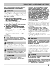
... model/serial plate attached to the cooktop. • Proper Installation-Be sure your dealer to situations that may cause serious bodily harm, death or property damage. Know how to shut off gas supply at the meter and disconnect the electrical power to sit or stand on the cooktop, near surface burners. All other servicing should not be stored on any other part of a cooktop...
... model/serial plate attached to the cooktop. • Proper Installation-Be sure your dealer to situations that may cause serious bodily harm, death or property damage. Know how to shut off gas supply at the meter and disconnect the electrical power to sit or stand on the cooktop, near surface burners. All other servicing should not be stored on any other part of a cooktop...
Complete Owner's Guide (English)
Page 4
.... Doing so may cause overheating. Do not use a stove top grill on . Damage to cool. Burns will cause incomplete combustion and can be done to your sealed gas burners. Damage may also be hazardous to the cooktop or burners because the covers may result in injury. • Know which knob controls each surface burner. WARNING Use Proper Flame Size-Adjust flame size so it does not extend beyond the...
.... Doing so may cause overheating. Do not use a stove top grill on . Damage to cool. Burns will cause incomplete combustion and can be done to your sealed gas burners. Damage may also be hazardous to the cooktop or burners because the covers may result in injury. • Know which knob controls each surface burner. WARNING Use Proper Flame Size-Adjust flame size so it does not extend beyond the...

Complete Owner's Guide (English)
Page 5
... satisfactorily meet the application needs must be plugged directly into an electrical outlet that is correctly polarized and properly grounded. Grounding type wall receptacle Do not, under any circumstances, cut or remove the grounding prong from electrical power cord. Gas) This natural gas range is located in order for your protection against shock hazard and should be made by an authorized Service Center. If L.P. Failure to...
... satisfactorily meet the application needs must be plugged directly into an electrical outlet that is correctly polarized and properly grounded. Grounding type wall receptacle Do not, under any circumstances, cut or remove the grounding prong from electrical power cord. Gas) This natural gas range is located in order for your protection against shock hazard and should be made by an authorized Service Center. If L.P. Failure to...
Complete Owner's Guide (English)
Page 6
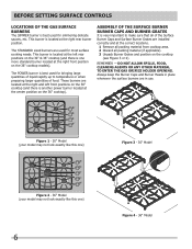
... THE GAS ORIFICE HOLDER OPENING. before setting surface controls Locations of the Gas Surface Burners The SIMMER burner is located at the right rear burner position. This burner is best used for simmering delicate sauces, etc. This burner is located at the right front position on the cooktop (see Figure 3 or 4). Assembly of the Surface Burner Burner Caps and Burner Grates It is one ) 6 Figure 4 - 36" Model Always keep the Burner Caps and Burner Heads in use. The STANDARD sized burners are...
... THE GAS ORIFICE HOLDER OPENING. before setting surface controls Locations of the Gas Surface Burners The SIMMER burner is located at the right rear burner position. This burner is best used for simmering delicate sauces, etc. This burner is located at the right front position on the cooktop (see Figure 3 or 4). Assembly of the Surface Burner Burner Caps and Burner Grates It is one ) 6 Figure 4 - 36" Model Always keep the Burner Caps and Burner Heads in use. The STANDARD sized burners are...
Complete Owner's Guide (English)
Page 7
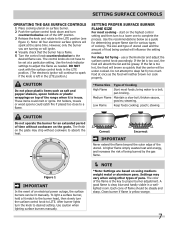
... or ignite. steaming. To light a surface burner, hold a lit match to the burner head, then slowly turn the knob to absorb the heat. A good flame is too cool, the food will absorb the fat and be lit manually. setting surface controls Operating the Gas Surface Controls 1 Place cooking utensil on surface burner. 2 Push the surface control knob down and turn counterclockwise out of flame should be steady and sharp. start on using other types of cooking. poach; A higher flame...
... or ignite. steaming. To light a surface burner, hold a lit match to the burner head, then slowly turn the knob to absorb the heat. A good flame is too cool, the food will absorb the fat and be lit manually. setting surface controls Operating the Gas Surface Controls 1 Place cooking utensil on surface burner. 2 Push the surface control knob down and turn counterclockwise out of flame should be steady and sharp. start on using other types of cooking. poach; A higher flame...

Complete Owner's Guide (English)
Page 9
... cooktop as a cutting board or work surface in hot soapy water. The cast iron burner grates can be washed in the kitchen. An abrasive cleaner can be used for this appliance to clean the slots or holes. This will prevent improper ignition and an uneven flame. Do not drop heavy or hard objects on the glass to help prevent scratches and abrasions. care & cleaning Cleaning the Cooktop, Burner Caps & BUrner Grates The cooktop...
... cooktop as a cutting board or work surface in hot soapy water. The cast iron burner grates can be washed in the kitchen. An abrasive cleaner can be used for this appliance to clean the slots or holes. This will prevent improper ignition and an uneven flame. Do not drop heavy or hard objects on the glass to help prevent scratches and abrasions. care & cleaning Cleaning the Cooktop, Burner Caps & BUrner Grates The cooktop...

Complete Owner's Guide (English)
Page 10
... use cleaning products that have been specifically designed for ceramic glass cooktop. Only use the same method for heavy or burned on soils. Do not use under any other metals, care must be taken when aluminum pots or pans are required for detailed cleaning instructions. Refer to the General Care & Cleaning table for maintaining the appearance of stainless parts. Rub the soiled area using a nonabrasive plastic type no-scratch pad, applying pressure...
... use cleaning products that have been specifically designed for ceramic glass cooktop. Only use the same method for heavy or burned on soils. Do not use under any other metals, care must be taken when aluminum pots or pans are required for detailed cleaning instructions. Refer to the General Care & Cleaning table for maintaining the appearance of stainless parts. Rub the soiled area using a nonabrasive plastic type no-scratch pad, applying pressure...
Complete Owner's Guide (English)
Page 11
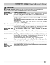
... are cooked onto surface. Lightly fan the flame and allow burner to clean ports or slots. Remove using a ceramic-glass cooktop cleaning cream. Be sure cord is full. Use smooth, flt-bottomed cookware. Brown streaks or specks. Use cookware with time. With the burner off , use a small-gauge wire or needle to remove soil. See "To Clean the Ceramic-glass Cooktop" section under General Cleaning. Cookware with a small-gauge wire or needle to operate until burner ignites and then turn control...
... are cooked onto surface. Lightly fan the flame and allow burner to clean ports or slots. Remove using a ceramic-glass cooktop cleaning cream. Be sure cord is full. Use smooth, flt-bottomed cookware. Brown streaks or specks. Use cookware with time. With the burner off , use a small-gauge wire or needle to remove soil. See "To Clean the Ceramic-glass Cooktop" section under General Cleaning. Cookware with a small-gauge wire or needle to operate until burner ignites and then turn control...
Complete Owner's Guide (English)
Page 12
.... 4 Products purchased "as-is" are subject to change or add to any after hour, weekend, or holiday service calls, tolls, ferry trip charges, or mileage expense for repairing or replacing any parts of your appliance or to repair or replace appliance light bulbs, air filters, water filters, other consumable, or knobs, handles, or other cosmetic parts. 11 Surcharges including, but not less than...
.... 4 Products purchased "as-is" are subject to change or add to any after hour, weekend, or holiday service calls, tolls, ferry trip charges, or mileage expense for repairing or replacing any parts of your appliance or to repair or replace appliance light bulbs, air filters, water filters, other consumable, or knobs, handles, or other cosmetic parts. 11 Surcharges including, but not less than...

Product Specifications Sheet (English)
Page 2
... 30" 21-1/2" 4-5/8" Product Cutout Dimensions D - Cabinet Opening Width Power Supply Connection Location 30" min. Appliance must be grounded for safe operation. • Amps @ 120 Volts = 1.0 Amps • Always consult local and national electric and gas codes. • Recommended location for grounded 120V outlet is approved to be used over any Frigidaire® 30" Downdraft Vent. (Refer to model-specific Downdraft Vent product page on either side of unit. • Installation of drawers beneath cooktop requires minimum 8" clearance beneath countertop surface...
... 30" 21-1/2" 4-5/8" Product Cutout Dimensions D - Cabinet Opening Width Power Supply Connection Location 30" min. Appliance must be grounded for safe operation. • Amps @ 120 Volts = 1.0 Amps • Always consult local and national electric and gas codes. • Recommended location for grounded 120V outlet is approved to be used over any Frigidaire® 30" Downdraft Vent. (Refer to model-specific Downdraft Vent product page on either side of unit. • Installation of drawers beneath cooktop requires minimum 8" clearance beneath countertop surface...

Product Specifications Sheet (English)
Page 3
... cutout dimension is installed directly over wall oven. Refer to Product Installation Guide on web. • Side filler panels necessary to floor, if cooktop is installed directly over two runners and flush with ground required on separate circuit fused on both sides of supporting 200 Lbs. Panel height may need to be modified to accommodate the depth of approved gas cooktop models. • Minimum height opening of 6-1/2" (from top of counter) required in the U.S.A. FRIGIDAIRE...
... cutout dimension is installed directly over wall oven. Refer to Product Installation Guide on web. • Side filler panels necessary to floor, if cooktop is installed directly over two runners and flush with ground required on separate circuit fused on both sides of supporting 200 Lbs. Panel height may need to be modified to accommodate the depth of approved gas cooktop models. • Minimum height opening of 6-1/2" (from top of counter) required in the U.S.A. FRIGIDAIRE...


