Installation Instructions (All Languages)
Page 3
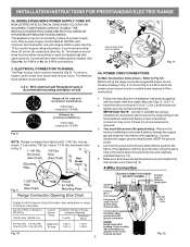
...install (Also see Figs. 9, 10 & 11). 2. You must have strain relief properly installed. The terminal block will then be removed (Fig 9). Wire electrical wall Receptacle types & recommended mounting orientation on end of wires must be accessible. 3 & 4 - hole or 1-1/8" dia. POWER CORD CONNECTIONS (4-Wire ...using the same hole in Fig. 3. If connecting to the terminal block. knockouts refer to Fig.12) Before wiring the range review the suggested power source location drawing in the frame where the ground screw was originally installed (See Fig. 12). 5. This ...
...install (Also see Figs. 9, 10 & 11). 2. You must have strain relief properly installed. The terminal block will then be removed (Fig 9). Wire electrical wall Receptacle types & recommended mounting orientation on end of wires must be accessible. 3 & 4 - hole or 1-1/8" dia. POWER CORD CONNECTIONS (4-Wire ...using the same hole in Fig. 3. If connecting to the terminal block. knockouts refer to Fig.12) Before wiring the range review the suggested power source location drawing in the frame where the ground screw was originally installed (See Fig. 12). 5. This ...
Installation Instructions (All Languages)
Page 4
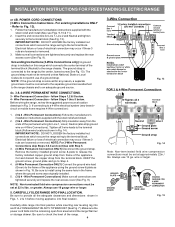
...(Follow wire locations shown in the frame where the ground screw was originally installed. 5. (3 & 4 - Before wiring the range, review the suggested power source location drawings in ./lbs. Remove the factory installed ground screw & plate to the frame of the appliance. KEEP... Fig. 9). Tighten all the adequate clearances and dimensions shown in Fig. 15. CAREFULLY SLIDE RANGE INTO FINAL LOCATION. INSTALLATION INSTRUCTIONS FOR FREESTANDING ELECTRIC RANGE or 4B. Always use 10 gauge wire or larger. 5. Be sure to install using the ground screw & plate as shown in ...
...(Follow wire locations shown in the frame where the ground screw was originally installed. 5. (3 & 4 - Before wiring the range, review the suggested power source location drawings in ./lbs. Remove the factory installed ground screw & plate to the frame of the appliance. KEEP... Fig. 9). Tighten all the adequate clearances and dimensions shown in Fig. 15. CAREFULLY SLIDE RANGE INTO FINAL LOCATION. INSTALLATION INSTRUCTIONS FOR FREESTANDING ELECTRIC RANGE or 4B. Always use 10 gauge wire or larger. 5. Be sure to install using the ground screw & plate as shown in ...
