Installation Instructions (All Languages)
Page 1
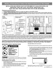
... these installation instructions before installing range. • Remove all packing material from the oven compartments before connecting the gas & electrical supply to reach over the surface elements, cabinet storage space above the elements should follow. Provide adequate clearances between the range and adjacent combustible surfaces. 2. Check for future reference. • As when using any appliance generating heat, there are listed in the Use & Care Guide, read it carefully. • Be sure your owner's guide...
... these installation instructions before installing range. • Remove all packing material from the oven compartments before connecting the gas & electrical supply to reach over the surface elements, cabinet storage space above the elements should follow. Provide adequate clearances between the range and adjacent combustible surfaces. 2. Check for future reference. • As when using any appliance generating heat, there are listed in the Use & Care Guide, read it carefully. • Be sure your owner's guide...
Installation Instructions (All Languages)
Page 2
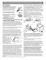
...; Power Supply Cord or • Copper Electrical Wiring & Metal Conduit (for cord kit ampere rating information. Level and Position Range - See Range Connection Opening Size Chart (Figs. 9 & 10) for hard wiring) NORMAL INSTALLATION STEPS 3/16" pilot hole 1-3/4" deep. If bracket is not available). Use a 5/16" nut-driver or flat head screwdriver to check your adjustments. IMPORTANT SAFETY WARNING To reduce the risk of tipping of the range, the range must be connected by properly installed Anti-Tip Bracket and...
...; Power Supply Cord or • Copper Electrical Wiring & Metal Conduit (for cord kit ampere rating information. Level and Position Range - See Range Connection Opening Size Chart (Figs. 9 & 10) for hard wiring) NORMAL INSTALLATION STEPS 3/16" pilot hole 1-3/4" deep. If bracket is not available). Use a 5/16" nut-driver or flat head screwdriver to check your adjustments. IMPORTANT SAFETY WARNING To reduce the risk of tipping of the range, the range must be connected by properly installed Anti-Tip Bracket and...
Installation Instructions (All Languages)
Page 3
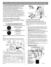
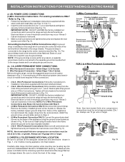
... for use either three (3) or four (4) conductors (See Fig. 8). MODELS REQUIRING POWER SUPPLY CORD KIT. Only a power supply cord kit rated at 125/250 volts minimum, and marked for Line 1, Line 2 and Neutral and tighten securely to Fig.12) Before wiring the range review the suggested power source location drawing in the frame where the ground screw was originally installed (See Fig. 12). 5. See Steps 4a. ELECTRICAL CONNECTION TO RANGE. POWER CORD CONNECTIONS (4-Wire Connection Instructions - Follow the manufacturer's installation instructions supplied...
... for use either three (3) or four (4) conductors (See Fig. 8). MODELS REQUIRING POWER SUPPLY CORD KIT. Only a power supply cord kit rated at 125/250 volts minimum, and marked for Line 1, Line 2 and Neutral and tighten securely to Fig.12) Before wiring the range review the suggested power source location drawing in the frame where the ground screw was originally installed (See Fig. 12). 5. See Steps 4a. ELECTRICAL CONNECTION TO RANGE. POWER CORD CONNECTIONS (4-Wire Connection Instructions - Follow the manufacturer's installation instructions supplied...
Installation Instructions (All Languages)
Page 4
... inserting rear leveling leg into the remaining open floor area behind the range Warmer or storage drawer. Fig. 15 The ground strap is removed for Line 1, Line 2 and Neutral and tighten securely to the terminal block. Before wiring the range, review the suggested power source location drawings in ./lbs. Follow the manufacturer's installation instructions supplied with the strain relief and install (Also see Figs. 9, 10 & 11). 2. POWER CORD CONNECTIONS (3-Wire Connection Instructions . Wire Permanent Connection...
... inserting rear leveling leg into the remaining open floor area behind the range Warmer or storage drawer. Fig. 15 The ground strap is removed for Line 1, Line 2 and Neutral and tighten securely to the terminal block. Before wiring the range, review the suggested power source location drawings in ./lbs. Follow the manufacturer's installation instructions supplied with the strain relief and install (Also see Figs. 9, 10 & 11). 2. POWER CORD CONNECTIONS (3-Wire Connection Instructions . Wire Permanent Connection...


