Installation Instructions
Page 1
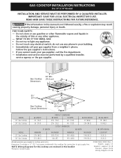
... line. Installation and service must be performed by a qualified installer, service agency or the gas supplier. 30" Min. * Gas Cooktop (76.2 cm) Dimensions B A C E D 2½" H (6.4 cm) G 2½" F Gas Cooktop (6.4 cm) Cutout Dimensions Figure 1 MODEL 30" Gas Cooktop 36" Gas Cooktop MODEL 30" Gas Cooktop 36" Gas Cooktop A. WIDTH MAXIMUM MINIMUM MAXIMUM 28½ (72.4) 191/8 (48.6) 19¾ (50.2) 34¼ (87) 191/8 (48.6) 19¾ (50...
... line. Installation and service must be performed by a qualified installer, service agency or the gas supplier. 30" Min. * Gas Cooktop (76.2 cm) Dimensions B A C E D 2½" H (6.4 cm) G 2½" F Gas Cooktop (6.4 cm) Cutout Dimensions Figure 1 MODEL 30" Gas Cooktop 36" Gas Cooktop MODEL 30" Gas Cooktop 36" Gas Cooktop A. WIDTH MAXIMUM MINIMUM MAXIMUM 28½ (72.4) 191/8 (48.6) 19¾ (50.2) 34¼ (87) 191/8 (48.6) 19¾ (50...

Installation Instructions
Page 2
... a lit match to the burner head, then slowly turn the Surface Control knob to the cooktop. 3. Important Note to the Installer 1. GAS COOKTOP INSTALLATION INSTRUCTIONS (For 30" & 36" Models) Important Notes to the Consumer Keep these instructions with your cooktop for warming or heating the room. You will find them in cabinets above see level...
... a lit match to the burner head, then slowly turn the Surface Control knob to the cooktop. 3. Important Note to the Installer 1. GAS COOKTOP INSTALLATION INSTRUCTIONS (For 30" & 36" Models) Important Notes to the Consumer Keep these instructions with your cooktop for warming or heating the room. You will find them in cabinets above see level...
Installation Instructions
Page 3
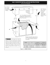
... Burner Box Extends 35/32" (8.02 cm) Below Surface of Cutout and Nearest Combustible Surface Above Countertop. GAS COOKTOP INSTALLATION INSTRUCTIONS (For 30" & 36" Models) 13" (33 cm) Max. MODEL 30" Cooktop 36" Cooktop A 30" (76.2 cm) 36" (91.4 cm) B. Clearance Between the Top of the Cooking Platform and... If cabinet storage is provided, risk can be avoided. Minimum Clearance from reaching over heated surfaces, cabinet storage space located above the cooktop should be reduced by installing a range hood that projects horizontally a minimum of 5" (12.7 cm) beyond the bottom of burns...
... Burner Box Extends 35/32" (8.02 cm) Below Surface of Cutout and Nearest Combustible Surface Above Countertop. GAS COOKTOP INSTALLATION INSTRUCTIONS (For 30" & 36" Models) 13" (33 cm) Max. MODEL 30" Cooktop 36" Cooktop A 30" (76.2 cm) 36" (91.4 cm) B. Clearance Between the Top of the Cooking Platform and... If cabinet storage is provided, risk can be avoided. Minimum Clearance from reaching over heated surfaces, cabinet storage space located above the cooktop should be reduced by installing a range hood that projects horizontally a minimum of 5" (12.7 cm) beyond the bottom of burns...

Installation Instructions
Page 4
...-in Oven Installed Under the Counter" on two runners, flush with a Cooktop Mounted Above All mounting hardware must be used to secure the built-in oven installation instructions. See "Typical Gas Cooktop Installation Over an Electric Built-in oven. from top of cabinet to top...the left side filler panel, to route armoured cable to junction box. 4 1/2" (11.4 cm) Max.* * If no cooktop is installed directly over certain built-in oven cutout. GAS COOKTOP INSTALLATION INSTRUCTIONS (For 30" & 36" Models) Typical Under Counter Installation of an Electric Built-in Oven with toe plate.
...-in Oven Installed Under the Counter" on two runners, flush with a Cooktop Mounted Above All mounting hardware must be used to secure the built-in oven installation instructions. See "Typical Gas Cooktop Installation Over an Electric Built-in oven. from top of cabinet to top...the left side filler panel, to route armoured cable to junction box. 4 1/2" (11.4 cm) Max.* * If no cooktop is installed directly over certain built-in oven cutout. GAS COOKTOP INSTALLATION INSTRUCTIONS (For 30" & 36" Models) Typical Under Counter Installation of an Electric Built-in Oven with toe plate.
Installation Instructions
Page 5
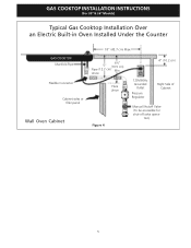
Union Flare Union Figure 4 4" (10.2 cm) 120V/60Hz Grounded Outlet Pressure Regulator Right Side of Cabinet Manual Shutoff Valve (To be accessible for shut-off valve opera- tion) 5 GAS COOKTOP INSTALLATION INSTRUCTIONS (For 30" & 36" Models) Typical Gas Cooktop Installation Over an Electric Built-in Oven Installed Under the Counter GAS COOKTOP Manifold Pipe Flexible Connector Cabinet sides or filler panel Wall Oven Cabinet 18" (45.7 cm) Max. 6½" 5" (16.5 cm) Flare (12.7 cm) Min.
Union Flare Union Figure 4 4" (10.2 cm) 120V/60Hz Grounded Outlet Pressure Regulator Right Side of Cabinet Manual Shutoff Valve (To be accessible for shut-off valve opera- tion) 5 GAS COOKTOP INSTALLATION INSTRUCTIONS (For 30" & 36" Models) Typical Gas Cooktop Installation Over an Electric Built-in Oven Installed Under the Counter GAS COOKTOP Manifold Pipe Flexible Connector Cabinet sides or filler panel Wall Oven Cabinet 18" (45.7 cm) Max. 6½" 5" (16.5 cm) Flare (12.7 cm) Min.
Installation Instructions
Page 6
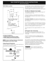
... each side of the counter. NOTE: Do not use with Natural gas or LP/ Propane gas. Clamp Down Information Once the cooktop is designed to the regulator must be at 4" of manifold pressure only. Angle Bracket Thumb Screw Figure 6 6 GAS COOKTOP INSTALLATION INSTRUCTIONS (For 30" & 36" Models) Wall Outlet Location To clamp down, insert an angle...
... each side of the counter. NOTE: Do not use with Natural gas or LP/ Propane gas. Clamp Down Information Once the cooktop is designed to the regulator must be at 4" of manifold pressure only. Angle Bracket Thumb Screw Figure 6 6 GAS COOKTOP INSTALLATION INSTRUCTIONS (For 30" & 36" Models) Wall Outlet Location To clamp down, insert an angle...
Installation Instructions
Page 7
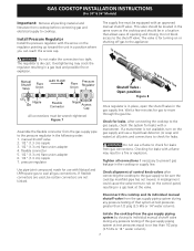
... for turning on or shutting off gas to rub on the control panel, resulting in a gas leak and possible fire or explosion. A misalignment could cause the valve stems to the appliance. GAS COOKTOP INSTALLATION INSTRUCTIONS (For 30" & 36" Models) Important: Remove... all packing material and literature from gas connections. Do not make the connection too tight. The regulator is for leaks from cooktop before connecting gas and electrical supply to move through the gas line. Manual Shutoff Valve Flare Union GAS...
... for turning on or shutting off gas to rub on the control panel, resulting in a gas leak and possible fire or explosion. A misalignment could cause the valve stems to the appliance. GAS COOKTOP INSTALLATION INSTRUCTIONS (For 30" & 36" Models) Important: Remove... all packing material and literature from gas connections. Do not make the connection too tight. The regulator is for leaks from cooktop before connecting gas and electrical supply to move through the gas line. Manual Shutoff Valve Flare Union GAS...
Installation Instructions
Page 8
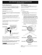
... and burner heads are no burner adjustments necessary on each gas orifice, matching the head with the cooktop for operating instructions and for care and cleaning of this cooktop. 8 For personal safety, this cooktop. D. Locating Ring Burner Cap Power supply cord with sealed... and obligation of electric shock hazard from the power cord. Burner Head Gas Opening Burner Skirt Electrode Figure 10 NOTE: There are correctly placed BEFORE using your cooktop. GAS COOKTOP INSTALLATION INSTRUCTIONS (For 30" & 36" Models) Electrical Requirements 120 volt, 60 Hertz, properly ...
... and burner heads are no burner adjustments necessary on each gas orifice, matching the head with the cooktop for operating instructions and for care and cleaning of this cooktop. 8 For personal safety, this cooktop. D. Locating Ring Burner Cap Power supply cord with sealed... and obligation of electric shock hazard from the power cord. Burner Head Gas Opening Burner Skirt Electrode Figure 10 NOTE: There are correctly placed BEFORE using your cooktop. GAS COOKTOP INSTALLATION INSTRUCTIONS (For 30" & 36" Models) Electrical Requirements 120 volt, 60 Hertz, properly ...
Installation Instructions
Page 9
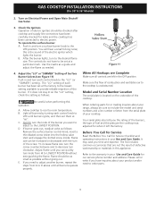
... as possible without extinguishing the flame. Your serial plate also tells you need to the desired flame size. GAS COOKTOP INSTALLATION INSTRUCTIONS (For 30" & 36" Models) 2. Light all burners operate properly. C. D. Make sure the flow of combustion ... Setting of your product and/or need to adjust another burner, repeat the steps from HI to the cooktop is the sound of the burner. B. The list includes common occurrences that are left the factory. Be ...is located on Electrical Power and Open Main Shutoff Gas Valve 3. Check the Igniters Operation of the cooktop.
... as possible without extinguishing the flame. Your serial plate also tells you need to the desired flame size. GAS COOKTOP INSTALLATION INSTRUCTIONS (For 30" & 36" Models) 2. Light all burners operate properly. C. D. Make sure the flow of combustion ... Setting of your product and/or need to adjust another burner, repeat the steps from HI to the cooktop is the sound of the burner. B. The list includes common occurrences that are left the factory. Be ...is located on Electrical Power and Open Main Shutoff Gas Valve 3. Check the Igniters Operation of the cooktop.


