Installation Instructions
Page 1
... inches and (cm). pages 19-26 Wiring Diagram 27-28 DEPTH BELOW COOKTOP* 8 (20.3) 8 (20.3) All dimensions are enclosed in this or any electrical switch; IMPORTANT: SAVE FOR LOCAL ELECTRICAL INSPECTOR'S USE. BOX LENGTH 21¾ (55.2) 4¼ (10.8) 27 (68.6) 21¾ (55.2) 4¼ (10.8) 33¼ (84.5) CUTOUT DIMENSIONS F. Installation and service must be performed by a qualified installer, service agency or the gas supplier. 30" Min. * Gas Cooktop...
... inches and (cm). pages 19-26 Wiring Diagram 27-28 DEPTH BELOW COOKTOP* 8 (20.3) 8 (20.3) All dimensions are enclosed in this or any electrical switch; IMPORTANT: SAVE FOR LOCAL ELECTRICAL INSPECTOR'S USE. BOX LENGTH 21¾ (55.2) 4¼ (10.8) 27 (68.6) 21¾ (55.2) 4¼ (10.8) 33¼ (84.5) CUTOUT DIMENSIONS F. Installation and service must be performed by a qualified installer, service agency or the gas supplier. 30" Min. * Gas Cooktop...

Installation Instructions
Page 2
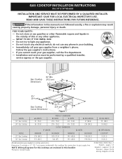
... use gasoline or other appliance. Use caution when lighting burners manually. • Do not store items of the cooktop without adequate ventilation can be shut off while gas line connections are certain safety precautions you should follow. The electrical power to reach over the surface burners, cabinet storage space above the burners should be hazardous. • Do not store or use of interest to the Installer 1. GAS COOKTOP INSTALLATION INSTRUCTIONS (For 30" & 36" Models...
... use gasoline or other appliance. Use caution when lighting burners manually. • Do not store items of the cooktop without adequate ventilation can be shut off while gas line connections are certain safety precautions you should follow. The electrical power to reach over the surface burners, cabinet storage space above the burners should be hazardous. • Do not store or use of interest to the Installer 1. GAS COOKTOP INSTALLATION INSTRUCTIONS (For 30" & 36" Models...
Installation Instructions
Page 3
... of Countertop. Clearance 30" (76.2 cm) Min. Clearance Between the Top of the Cooking Platform and Unprotected Wood or Metal Cabinet B C 24" (61 cm) To eliminate the risk of burns or fire from reaching over heated surfaces, cabinet storage space located above the cooktop should be reduced by installing a range hood that projects horizontally a minimum of 5" (12.7 cm) beyond the bottom of the cabinets. GAS COOKTOP INSTALLATION INSTRUCTIONS (For 30" & 36" Models...
... of Countertop. Clearance 30" (76.2 cm) Min. Clearance Between the Top of the Cooking Platform and Unprotected Wood or Metal Cabinet B C 24" (61 cm) To eliminate the risk of burns or fire from reaching over heated surfaces, cabinet storage space located above the cooktop should be reduced by installing a range hood that projects horizontally a minimum of 5" (12.7 cm) beyond the bottom of the cabinets. GAS COOKTOP INSTALLATION INSTRUCTIONS (For 30" & 36" Models...

Installation Instructions
Page 4
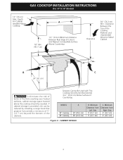
... the cabinets. G Side filler panels are necessary to the built-in oven. This cooktop may be located approx. 3" to junction box. 4 1/2" (11.4 cm) Max.* * If no cooktop is allowed. ** 32" (81.3 cm) min. See "Typical Gas Cooktop Installation Over an Electric Built-in Oven Installed Under the Counter" on two runners, flush with a Cooktop Mounted Above All mounting hardware must be capable of supporting 150 lbs. Cut an opening in wood base minimum...
... the cabinets. G Side filler panels are necessary to the built-in oven. This cooktop may be located approx. 3" to junction box. 4 1/2" (11.4 cm) Max.* * If no cooktop is allowed. ** 32" (81.3 cm) min. See "Typical Gas Cooktop Installation Over an Electric Built-in Oven Installed Under the Counter" on two runners, flush with a Cooktop Mounted Above All mounting hardware must be capable of supporting 150 lbs. Cut an opening in wood base minimum...
Installation Instructions
Page 5
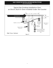
tion) 5 Union Flare Union Figure 4 4" (10.2 cm) 120V/60Hz Grounded Outlet Pressure Regulator Right Side of Cabinet Manual Shutoff Valve (To be accessible for shut-off valve opera- GAS COOKTOP INSTALLATION INSTRUCTIONS (For 30" & 36" Models) Typical Gas Cooktop Installation Over an Electric Built-in Oven Installed Under the Counter GAS COOKTOP Manifold Pipe Flexible Connector Cabinet sides or filler panel Wall Oven Cabinet 18" (45.7 cm) Max. 6½" 5" (16.5 cm) Flare (12.7 cm) Min.
tion) 5 Union Flare Union Figure 4 4" (10.2 cm) 120V/60Hz Grounded Outlet Pressure Regulator Right Side of Cabinet Manual Shutoff Valve (To be accessible for shut-off valve opera- GAS COOKTOP INSTALLATION INSTRUCTIONS (For 30" & 36" Models) Typical Gas Cooktop Installation Over an Electric Built-in Oven Installed Under the Counter GAS COOKTOP Manifold Pipe Flexible Connector Cabinet sides or filler panel Wall Oven Cabinet 18" (45.7 cm) Max. 6½" 5" (16.5 cm) Flare (12.7 cm) Min.
Installation Instructions
Page 6
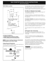
... the cooktop for the conversion. Angle Bracket Thumb Screw Figure 6 6 The regulator is designed to the regulator must be no more than the regulator manifold pressure setting. Figure 5 Cooktop Installation 1. Provide an Adequate Gas Supply This cooktop is set for use caulking compound; The qualified agency performing this work assumes responsibility for damage. 2. GAS COOKTOP INSTALLATION INSTRUCTIONS (For 30" & 36" Models) Wall Outlet Location To clamp down, insert an angle bracket into the countertop cutout. For...
... the cooktop for the conversion. Angle Bracket Thumb Screw Figure 6 6 The regulator is designed to the regulator must be no more than the regulator manifold pressure setting. Figure 5 Cooktop Installation 1. Provide an Adequate Gas Supply This cooktop is set for use caulking compound; The qualified agency performing this work assumes responsibility for damage. 2. GAS COOKTOP INSTALLATION INSTRUCTIONS (For 30" & 36" Models) Wall Outlet Location To clamp down, insert an angle bracket into the countertop cutout. For...
Installation Instructions
Page 7
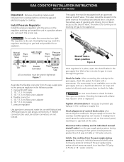
...). 7 A misalignment could cause the valve stems to rub on the regulator pointing up toward the unit in a position where you can reach the access cap. Install Pressure Regulator Install the pressure regulator with Natural and LP/Propane gas to seal all gas connections. pressure regulator Use pipe-joint compound made for leaks. Do not block access to move through the gas line. GAS COOKTOP INSTALLATION INSTRUCTIONS (For 30" & 36" Models) Important: Remove all packing material and literature...
...). 7 A misalignment could cause the valve stems to rub on the regulator pointing up toward the unit in a position where you can reach the access cap. Install Pressure Regulator Install the pressure regulator with Natural and LP/Propane gas to seal all gas connections. pressure regulator Use pipe-joint compound made for leaks. Do not block access to move through the gas line. GAS COOKTOP INSTALLATION INSTRUCTIONS (For 30" & 36" Models) Important: Remove all packing material and literature...
Installation Instructions
Page 8
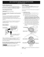
.... GAS COOKTOP INSTALLATION INSTRUCTIONS (For 30" & 36" Models) Electrical Requirements 120 volt, 60 Hertz, properly grounded branch circuit protected by a properly grounded 3prong wall receptacle. Do not use an extension cord with 3prong grounding plug. Grounding Instructions IMPORTANT Please read carefully. The wall receptacle and circuit should be hot enough to have it replaced by a 15 amp circuit breaker or time delay fuse. A. Make sure electrode fits correctly into slot in burner head...
.... GAS COOKTOP INSTALLATION INSTRUCTIONS (For 30" & 36" Models) Electrical Requirements 120 volt, 60 Hertz, properly grounded branch circuit protected by a properly grounded 3prong wall receptacle. Do not use an extension cord with 3prong grounding plug. Grounding Instructions IMPORTANT Please read carefully. The wall receptacle and circuit should be hot enough to have it replaced by a 15 amp circuit breaker or time delay fuse. A. Make sure electrode fits correctly into slot in burner head...
Installation Instructions
Page 9
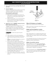
... "SIMMER") setting. Flame size can quickly turn clockwise. Flame should be checked after cooktop and supply line connectors have to decrease turn knob from HI to LITE until burners ignite, and then set at "HI". C. GAS COOKTOP INSTALLATION INSTRUCTIONS (For 30" & 36" Models) 2. Turn on the underside of Surface Burner Valves (see Figure 11) Push in and turn the knob of the burner you have inquiries about your product and/or need to adjust another burner, repeat the steps from the serial...
... "SIMMER") setting. Flame size can quickly turn clockwise. Flame should be checked after cooktop and supply line connectors have to decrease turn knob from HI to LITE until burners ignite, and then set at "HI". C. GAS COOKTOP INSTALLATION INSTRUCTIONS (For 30" & 36" Models) 2. Turn on the underside of Surface Burner Valves (see Figure 11) Push in and turn the knob of the burner you have inquiries about your product and/or need to adjust another burner, repeat the steps from the serial...


