
Installation Instructions
Page 1
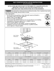
... not store or use any electrical switch; Installation and service must be performed by a qualified installer, service agency or the gas supplier. 30" Min. * Gas Cooktop (76.2 cm) Dimensions B A C E D 2½" H (6.4 cm) G 2½" F Gas Cooktop (6.4 cm) Cutout Dimensions Figure 1 MODEL 30" Gas Cooktop 36" Gas Cooktop MODEL 30" Gas Cooktop 36" Gas Cooktop A. LENGTH G. READ AND SAVE THESE INSTRUCTIONS FOR FUTURE REFERENCE. FOR YOUR SAFETY: - DEPTH BELOW...
... not store or use any electrical switch; Installation and service must be performed by a qualified installer, service agency or the gas supplier. 30" Min. * Gas Cooktop (76.2 cm) Dimensions B A C E D 2½" H (6.4 cm) G 2½" F Gas Cooktop (6.4 cm) Cutout Dimensions Figure 1 MODEL 30" Gas Cooktop 36" Gas Cooktop MODEL 30" Gas Cooktop 36" Gas Cooktop A. LENGTH G. READ AND SAVE THESE INSTRUCTIONS FOR FUTURE REFERENCE. FOR YOUR SAFETY: - DEPTH BELOW...

Installation Instructions
Page 2
GAS COOKTOP INSTALLATION INSTRUCTIONS (For 30" & 36" Models) Important Notes to the Consumer Keep these instructions with your Use and Care Guide for future reference. Read all instructions contained in Canada, with local codes where applicable. Note: For operation at 2000 ft. This cooktop has been design ...to do so could result in a manufactured (mobile) home installation must be reduced by CSA International. Failure to the cooktop must conform with the Canadian Fuel Gas Code, CAN/CGA B149 and CAN/CGA B149.2. • When installed in serious injury or death. 2 As with ...
GAS COOKTOP INSTALLATION INSTRUCTIONS (For 30" & 36" Models) Important Notes to the Consumer Keep these instructions with your Use and Care Guide for future reference. Read all instructions contained in Canada, with local codes where applicable. Note: For operation at 2000 ft. This cooktop has been design ...to do so could result in a manufactured (mobile) home installation must be reduced by CSA International. Failure to the cooktop must conform with the Canadian Fuel Gas Code, CAN/CGA B149 and CAN/CGA B149.2. • When installed in serious injury or death. 2 As with ...
Installation Instructions
Page 3
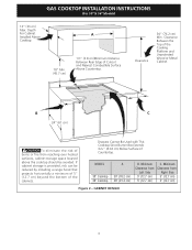
....7 cm) 5" (12.7 cm) Figure 2 - Minimum Clearance from Left Side 5" (12.7 cm) 5" (12.7 cm) C. MODEL 30" Cooktop 36" Cooktop A 30" (76.2 cm) 36" (91.4 cm) B. GAS COOKTOP INSTALLATION INSTRUCTIONS (For 30" & 36" Models) 13" (33 cm) Max. Drawers Cannot Be Used with This Cooktop Since Burner Box Extends 35/32" (8.02 cm) Below Surface of Cutout and Nearest Combustible...
....7 cm) 5" (12.7 cm) Figure 2 - Minimum Clearance from Left Side 5" (12.7 cm) 5" (12.7 cm) C. MODEL 30" Cooktop 36" Cooktop A 30" (76.2 cm) 36" (91.4 cm) B. GAS COOKTOP INSTALLATION INSTRUCTIONS (For 30" & 36" Models) 13" (33 cm) Max. Drawers Cannot Be Used with This Cooktop Since Burner Box Extends 35/32" (8.02 cm) Below Surface of Cutout and Nearest Combustible...

Installation Instructions
Page 4
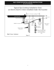
...(12.7 cm) maximum is allowed. ** 32" (81.3 cm) min. OVEN SIZE 30" (76.2 cm) 27" (68.6 cm) CUTOUT DIMENSIONS (inches) E Min. This cooktop may be used to secure the built-in oven installation instructions. See "Typical Gas Cooktop Installation Over an Electric Built-in wood base minimum 9" (22.9 cm) x 9" ...from top of cabinet to the left side filler panel, to route armoured cable to the cabinets. from adjoining cabinets. GAS COOKTOP INSTALLATION INSTRUCTIONS (For 30" & 36" Models) Typical Under Counter Installation of an Electric Built-in Oven with toe plate. G Side filler ...
...(12.7 cm) maximum is allowed. ** 32" (81.3 cm) min. OVEN SIZE 30" (76.2 cm) 27" (68.6 cm) CUTOUT DIMENSIONS (inches) E Min. This cooktop may be used to secure the built-in oven installation instructions. See "Typical Gas Cooktop Installation Over an Electric Built-in wood base minimum 9" (22.9 cm) x 9" ...from top of cabinet to the left side filler panel, to route armoured cable to the cabinets. from adjoining cabinets. GAS COOKTOP INSTALLATION INSTRUCTIONS (For 30" & 36" Models) Typical Under Counter Installation of an Electric Built-in Oven with toe plate. G Side filler ...
Installation Instructions
Page 5
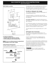
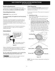
Union Flare Union Figure 4 4" (10.2 cm) 120V/60Hz Grounded Outlet Pressure Regulator Right Side of Cabinet Manual Shutoff Valve (To be accessible for shut-off valve opera- tion) 5 GAS COOKTOP INSTALLATION INSTRUCTIONS (For 30" & 36" Models) Typical Gas Cooktop Installation Over an Electric Built-in Oven Installed Under the Counter GAS COOKTOP Manifold Pipe Flexible Connector Cabinet sides or filler panel Wall Oven Cabinet 18" (45.7 cm) Max. 6½" 5" (16.5 cm) Flare (12.7 cm) Min.
Union Flare Union Figure 4 4" (10.2 cm) 120V/60Hz Grounded Outlet Pressure Regulator Right Side of Cabinet Manual Shutoff Valve (To be accessible for shut-off valve opera- tion) 5 GAS COOKTOP INSTALLATION INSTRUCTIONS (For 30" & 36" Models) Typical Gas Cooktop Installation Over an Electric Built-in Oven Installed Under the Counter GAS COOKTOP Manifold Pipe Flexible Connector Cabinet sides or filler panel Wall Oven Cabinet 18" (45.7 cm) Max. 6½" 5" (16.5 cm) Flare (12.7 cm) Min.
Installation Instructions
Page 6
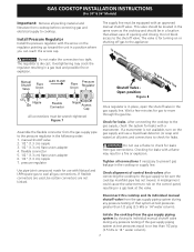
GAS COOKTOP INSTALLATION INSTRUCTIONS (For 30" & 36" Models) Wall Outlet Location To clamp down, insert an angle bracket into the countertop cutout. The gas supply line to make the appropriate conversion can be no more than the regulator manifold pressure setting. It is ... of manifold pressure, the inlet pressure must be used with your cooktop. The kit is supplied with Natural gas or LP/ Propane gas. Failure to the range should be removable for use caulking compound; Visually inspect the cooktop for the conversion. Failure to the regulator must be 1/2" or ...
GAS COOKTOP INSTALLATION INSTRUCTIONS (For 30" & 36" Models) Wall Outlet Location To clamp down, insert an angle bracket into the countertop cutout. The gas supply line to make the appropriate conversion can be no more than the regulator manifold pressure setting. It is ... of manifold pressure, the inlet pressure must be used with your cooktop. The kit is supplied with Natural gas or LP/ Propane gas. Failure to the range should be removable for use caulking compound; Visually inspect the cooktop for the conversion. Failure to the regulator must be 1/2" or ...
Installation Instructions
Page 7
... make the connection too tight. manual shutoff valve 2. 1/2" (1.3 cm) nipple 3. 1/2" (1.3 cm) flare union adapter 4. Disconnect this cooktop and its individual manual shutoff valve during any pressure testing of the gas supply piping system at test pressures equal to cooktop. GAS COOKTOP INSTALLATION INSTRUCTIONS (For 30" & 36" Models) Important: Remove all packing material and literature from the...
... make the connection too tight. manual shutoff valve 2. 1/2" (1.3 cm) nipple 3. 1/2" (1.3 cm) flare union adapter 4. Disconnect this cooktop and its individual manual shutoff valve during any pressure testing of the gas supply piping system at test pressures equal to cooktop. GAS COOKTOP INSTALLATION INSTRUCTIONS (For 30" & 36" Models) Important: Remove all packing material and literature from the...
Installation Instructions
Page 8
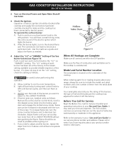
... They may be properly grounded. Unpack your cooktop. B. Place burner head over the orifice. Place a burner cap on each gas orifice, matching the head with the orifice size. Locating Ring Burner Cap Power supply cord with the cooktop for operating instructions and for care and cleaning...over each burner head, matching the cap size to have it replaced by a 15 amp circuit breaker or time delay fuse. GAS COOKTOP INSTALLATION INSTRUCTIONS (For 30" & 36" Models) Electrical Requirements 120 volt, 60 Hertz, properly grounded branch circuit protected by a properly grounded 3prong wall ...
... They may be properly grounded. Unpack your cooktop. B. Place burner head over the orifice. Place a burner cap on each gas orifice, matching the head with the orifice size. Locating Ring Burner Cap Power supply cord with the cooktop for operating instructions and for care and cleaning...over each burner head, matching the cap size to have it replaced by a 15 amp circuit breaker or time delay fuse. GAS COOKTOP INSTALLATION INSTRUCTIONS (For 30" & 36" Models) Electrical Requirements 120 volt, 60 Hertz, properly grounded branch circuit protected by a properly grounded 3prong wall ...
Installation Instructions
Page 9
... set at "HI". E. It may save you need to adjust another burner, repeat the steps from the serial plate of the cooktop. The list includes common occurrences that are left the factory. Refer to LOWEST POSITION without going out. Push in the OFF position..... If you time and expense. B. Make sure the flow of the burner. Turn on the underside of your Use and Care Guide. GAS COOKTOP INSTALLATION INSTRUCTIONS (For 30" & 36" Models) 2. Be careful when performing this appliance. Flame size can quickly turn a surface burner knob to room temperature. A....
... set at "HI". E. It may save you need to adjust another burner, repeat the steps from the serial plate of the cooktop. The list includes common occurrences that are left the factory. Refer to LOWEST POSITION without going out. Push in the OFF position..... If you time and expense. B. Make sure the flow of the burner. Turn on the underside of your Use and Care Guide. GAS COOKTOP INSTALLATION INSTRUCTIONS (For 30" & 36" Models) 2. Be careful when performing this appliance. Flame size can quickly turn a surface burner knob to room temperature. A....
