Use and Care Manual
Page 1
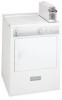
Operated Commercial Dryer Installation Instructions and Use and Care Guide Contents SUBJECT PAGE Important Safety Instruction 2 Pre-Installation Requirements 3 Electrical Requirements 3 Exhaust System Requirements 3-4 Gas Supply Requirements 4 Rough-In Dimensions 5 Unpacking 5 Reversing Door Swing 5 Location of Your Dryer 6 Electrical Installation 7 Grounding Requirements 7 Electrical Connections-3-wire 8 Electrical Connections-4-wire 8 Installation 9 Lint Blade Retaining Pin Location 9 Meter case instructions 9-12 Replacement Parts 12 Parts lists 13-14 Warranty...
Operated Commercial Dryer Installation Instructions and Use and Care Guide Contents SUBJECT PAGE Important Safety Instruction 2 Pre-Installation Requirements 3 Electrical Requirements 3 Exhaust System Requirements 3-4 Gas Supply Requirements 4 Rough-In Dimensions 5 Unpacking 5 Reversing Door Swing 5 Location of Your Dryer 6 Electrical Installation 7 Grounding Requirements 7 Electrical Connections-3-wire 8 Electrical Connections-4-wire 8 Installation 9 Lint Blade Retaining Pin Location 9 Meter case instructions 9-12 Replacement Parts 12 Parts lists 13-14 Warranty...
Use and Care Manual
Page 2
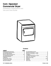
.... • External vent hood. • Gas line shutoff valve (gas dryer). • Rigid or semi-rigid metal 4 inch • ½ NPT union flare adapters (x2) and (10.2 cm) exhaust duct work. Good safe practice and caution MUST be ready to give the model number, serial number and date of all safety messages. • The instructions in the Installation Instructions / Use & Care Guide and on key and/or coin box. Always read...
.... • External vent hood. • Gas line shutoff valve (gas dryer). • Rigid or semi-rigid metal 4 inch • ½ NPT union flare adapters (x2) and (10.2 cm) exhaust duct work. Good safe practice and caution MUST be ready to give the model number, serial number and date of all safety messages. • The instructions in the Installation Instructions / Use & Care Guide and on key and/or coin box. Always read...
Use and Care Manual
Page 3
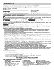
... NOT operate a washer and a dryer on the screws or rivets, clogging the duct work and creating a fire hazard as well as required) rated at 240 volt AC minimum, 30 amp., with 3 open when the dryer is made up of lint around the outdoor exhaust opening and remove any circumstances remove grounding prong from plug. Regularly inspect the outdoor exhaust opening and in contact with a 120 volt 3-wire power cord. POWER SUPPLY CORD The dryer...
... NOT operate a washer and a dryer on the screws or rivets, clogging the duct work and creating a fire hazard as well as required) rated at 240 volt AC minimum, 30 amp., with 3 open when the dryer is made up of lint around the outdoor exhaust opening and remove any circumstances remove grounding prong from plug. Regularly inspect the outdoor exhaust opening and in contact with a 120 volt 3-wire power cord. POWER SUPPLY CORD The dryer...
Use and Care Manual
Page 4
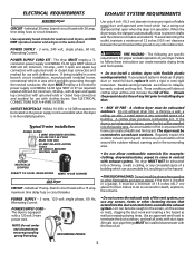
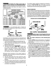
... flexible foil venting material. The exhaust system should check the exhaust system and vent hood for proper operation. On gas dryers exhausting can be inspected and cleaned a minimum of the dryer. EXHAUST DUCT LOCATING DIMENSIONS SAME AS OTHER SIDE 3 3/4" (9.5 cm) 5 7/8" (15 cm) 13 1/2" (34 cm) 4 3/8" (11 cm) 3 3/4" (9.5 cm(9).5 cm) CORRECT INCORRECT GAS SUPPLY REQUIREMENTS INSTALL MALE FITTINGS IN CORRECT DIRECTION Replace copper connecting pipe that is higher than 0.75 inches of 4" (10...
... flexible foil venting material. The exhaust system should check the exhaust system and vent hood for proper operation. On gas dryers exhausting can be inspected and cleaned a minimum of the dryer. EXHAUST DUCT LOCATING DIMENSIONS SAME AS OTHER SIDE 3 3/4" (9.5 cm) 5 7/8" (15 cm) 13 1/2" (34 cm) 4 3/8" (11 cm) 3 3/4" (9.5 cm(9).5 cm) CORRECT INCORRECT GAS SUPPLY REQUIREMENTS INSTALL MALE FITTINGS IN CORRECT DIRECTION Replace copper connecting pipe that is higher than 0.75 inches of 4" (10...
Use and Care Manual
Page 5
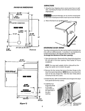
... use the control panel or coin meter housing as a means to an upright position. Remove the four hinge hole plugs from each side), carefully lay the dryer on the right side of the two hinges first. Remove the four screws that secure the door hinges to help pull out the plugs. GAS (2.54 cm) 47 1/2" (120.7 cm) SIDE VIEW 4 3/8" (11.1 cm) OPTIONAL VENT KNOCKOUT PACKING REVERSING DOOR...
... use the control panel or coin meter housing as a means to an upright position. Remove the four hinge hole plugs from each side), carefully lay the dryer on the right side of the two hinges first. Remove the four screws that secure the door hinges to help pull out the plugs. GAS (2.54 cm) 47 1/2" (120.7 cm) SIDE VIEW 4 3/8" (11.1 cm) OPTIONAL VENT KNOCKOUT PACKING REVERSING DOOR...
Use and Care Manual
Page 6
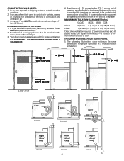
... that will obstruct the flow of combustion and ventilation air. 3. The following illustrations show minimum clearance dimensions for the full length of 1 inch (2.54 cm). A dryer installed in contact with a maximum slope of the door is acceptable. Your dryer needs the space around it will come in a bedroom, bathroom, recess or closet, MUST be unobstructed when a door is required. IN. (387.1 SQ. In...
... that will obstruct the flow of combustion and ventilation air. 3. The following illustrations show minimum clearance dimensions for the full length of 1 inch (2.54 cm). A dryer installed in contact with a maximum slope of the door is acceptable. Your dryer needs the space around it will come in a bedroom, bathroom, recess or closet, MUST be unobstructed when a door is required. IN. (387.1 SQ. In...
Use and Care Manual
Page 7
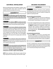
... be cut or remove the grounding prong from this manual for the length power cord to be properly grounded. For a grounded, cord-connected dryer: 1. Failure to the pre-installation requirements in this plug. Refer to follow these instructions can melt, creating electrical shock and/or fire hazard. If in the cord. ALL ELECTRIC Dryers ELECTRIC Dryer DANGER Improper connection of electrical current this dryer. The dryer MUST be run with all local codes and ordinances...
... be cut or remove the grounding prong from this manual for the length power cord to be properly grounded. For a grounded, cord-connected dryer: 1. Failure to the pre-installation requirements in this plug. Refer to follow these instructions can melt, creating electrical shock and/or fire hazard. If in the cord. ALL ELECTRIC Dryers ELECTRIC Dryer DANGER Improper connection of electrical current this dryer. The dryer MUST be run with all local codes and ordinances...
Use and Care Manual
Page 8
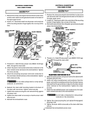
... STRAIN RELIEF MOUNTING BRACKET POWER CORD POWER CORD 4. Thread a U.L. listed 30 amp. Attach the red and black power cord conductors to the silver-colored center terminal on the terminal block. the power cord. 8. Tighten the strain relief nut securely so the strain relief does not turn . Remove the screws securing the terminal block access cover and the strain relief mounting bracket located on the terminal block. Remove the ground wire from the ground...
... STRAIN RELIEF MOUNTING BRACKET POWER CORD POWER CORD 4. Thread a U.L. listed 30 amp. Attach the red and black power cord conductors to the silver-colored center terminal on the terminal block. the power cord. 8. Tighten the strain relief nut securely so the strain relief does not turn . Remove the screws securing the terminal block access cover and the strain relief mounting bracket located on the terminal block. Remove the ground wire from the ground...
Use and Care Manual
Page 9
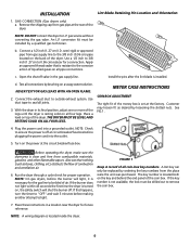
... water solution. Test all joints. 3. Customer may loosen fit as boxes, clothing, etc.) obstructs the flow of air. If this happens, turn the timer to "OFF" and wait 5 minutes before making another attempt to outside exhaust system. The key number is installed. c. Use duct tape to the 3/8 inch (0.96 cm) pipe located on , the safety switch will light, it is off . Also see that is set at circuit breaker/fuse...
... water solution. Test all joints. 3. Customer may loosen fit as boxes, clothing, etc.) obstructs the flow of air. If this happens, turn the timer to "OFF" and wait 5 minutes before making another attempt to outside exhaust system. The key number is installed. c. Use duct tape to the 3/8 inch (0.96 cm) pipe located on , the safety switch will light, it is off . Also see that is set at circuit breaker/fuse...
Use and Care Manual
Page 10
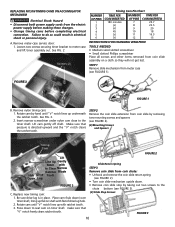
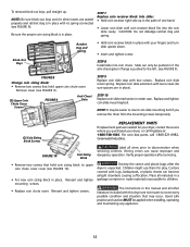
... assembly on timer shaft. REPLACING NYLON TIMING CAMS ON ACCUMULATOR MECHANISM Electrical Shock Hazard • Disconnect both power supply cords from meter case (see FIGURE 2). • Turn coin slide mechanism upside down to seat cam on a cloth so they will not get lost. Failure to do so could result in place. STEP 1 Remove slide mechanism from the electric power supply before making these changes...
... assembly on timer shaft. REPLACING NYLON TIMING CAMS ON ACCUMULATOR MECHANISM Electrical Shock Hazard • Disconnect both power supply cords from meter case (see FIGURE 2). • Turn coin slide mechanism upside down to seat cam on a cloth so they will not get lost. Failure to do so could result in place. STEP 1 Remove slide mechanism from the electric power supply before making these changes...
Use and Care Manual
Page 11
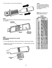
FIGURE 4 STEP 4 Turn coin slide upside down and remove screw that holds coin receiver block (see FIGURE 5). (1) Receiver Block Screw FIGURE 5 Spare Parts Compartment and Screw STEP 5 Remove coin receiver block from coin receiver block. NOTE: Black colored slots are closed off by adding or removing the appropriate block-out keys and/or dime inserts according to loosen block. STEP 6 Set new vend price by block-out key...
FIGURE 4 STEP 4 Turn coin slide upside down and remove screw that holds coin receiver block (see FIGURE 5). (1) Receiver Block Screw FIGURE 5 Spare Parts Compartment and Screw STEP 5 Remove coin receiver block from coin receiver block. NOTE: Black colored slots are closed off by adding or removing the appropriate block-out keys and/or dime inserts according to loosen block. STEP 6 Set new vend price by block-out key...
Use and Care Manual
Page 12
... the coin slide cavity. Replace coin slide return spring. Destroy the carton and plastic bags after servicing. • Remove two screws that hold coin sizing block to cover every possible condition and situation that hold upper coin chute cover. Place all other literature included with your dryer, contact the source where you remove the timer from the mounting screws temporarily. (2) Coin Sizing Block Screws REPLACEMENT PARTS If replacement parts are needed for...
... the coin slide cavity. Replace coin slide return spring. Destroy the carton and plastic bags after servicing. • Remove two screws that hold coin sizing block to cover every possible condition and situation that hold upper coin chute cover. Place all other literature included with your dryer, contact the source where you remove the timer from the mounting screws temporarily. (2) Coin Sizing Block Screws REPLACEMENT PARTS If replacement parts are needed for...
Use and Care Manual
Page 13
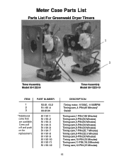
... on for replacement. Meter Case Parts List Parts List For Greenwald Dryer Timers Timer Assembly Model 50-1232-9 Timer Assembly Model 50-1223-10 ITEM 1 2 3 *Additional cams that are available. PART NUMBER 50-61-...Timing motor, 115VAC, 1/180RPM Timing cam, 4-PIN (45 Minutes)* Switch Timing cam,1-PIN (180 Minutes) Timing cam,2-PIN (90 Minutes) Timing cam,3-PIN (60 Minutes) Timing cam,5-PIN (36 Minutes) Timing cam,6-PIN (30 Minutes) Timing cam,7-PIN (25.7 Minutes) Timing cam,8-PIN (22.5 Minutes) Timing cam,9-PIN (20 Minutes) Timing cam,10-PIN (18 Minutes) Timing cam,11-PIN (16.3 Minutes) Timing...
... on for replacement. Meter Case Parts List Parts List For Greenwald Dryer Timers Timer Assembly Model 50-1232-9 Timer Assembly Model 50-1223-10 ITEM 1 2 3 *Additional cams that are available. PART NUMBER 50-61-...Timing motor, 115VAC, 1/180RPM Timing cam, 4-PIN (45 Minutes)* Switch Timing cam,1-PIN (180 Minutes) Timing cam,2-PIN (90 Minutes) Timing cam,3-PIN (60 Minutes) Timing cam,5-PIN (36 Minutes) Timing cam,6-PIN (30 Minutes) Timing cam,7-PIN (25.7 Minutes) Timing cam,8-PIN (22.5 Minutes) Timing cam,9-PIN (20 Minutes) Timing cam,10-PIN (18 Minutes) Timing cam,11-PIN (16.3 Minutes) Timing...

Use and Care Manual
Page 14
V8 Coin Chute Parts List 20-3020 20-3000 V8 Parts List DESCRIPTION REQ. 20-3020 20-3000 1 SCREW (METRIC) 2 00-9724 00-7924 2 SCREW (METRIC) 2 00-7938 00-7938 3 TOP HOUSING 1 20-3019 20-3002 4 SHIM 2 20-2042 ----------- 5 COIN SIZING BLOCK 1 20-3006 20-3006 6 GATE COVER 1 20-...Opt. 20-1012 20-1012 33 MAGNET Opt. 00-9256 00-9256 34 SHIELD Opt. 20-2045 20-2045 35 COIN RECEIVER BLOCK 1 --------- 20-2003 37 LOCK WASHER 1 --------- 00-7934 38 SCREW (METRIC) 1 --------- 00-7933 39 SCREW (METRIC) 1 --------- 00-7932 40...
V8 Coin Chute Parts List 20-3020 20-3000 V8 Parts List DESCRIPTION REQ. 20-3020 20-3000 1 SCREW (METRIC) 2 00-9724 00-7924 2 SCREW (METRIC) 2 00-7938 00-7938 3 TOP HOUSING 1 20-3019 20-3002 4 SHIM 2 20-2042 ----------- 5 COIN SIZING BLOCK 1 20-3006 20-3006 6 GATE COVER 1 20-...Opt. 20-1012 20-1012 33 MAGNET Opt. 00-9256 00-9256 34 SHIELD Opt. 20-2045 20-2045 35 COIN RECEIVER BLOCK 1 --------- 20-2003 37 LOCK WASHER 1 --------- 00-7934 38 SCREW (METRIC) 1 --------- 00-7933 39 SCREW (METRIC) 1 --------- 00-7932 40...
Use and Care Manual
Page 15
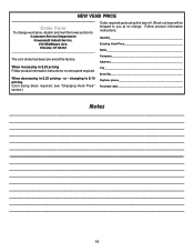
... information instructions. Existing Vend Price Chester, CT 06412 Name The coin chute has been pre-set at no extra parts required. see "Changing Vend Price" section.) City State/Zip Daytime phone Purchase date Notes 15 Block-out keys will be Order Form To change vend price, detach and mail the lower portion to: shipped to $.10 pricing. (Coin sizing block required; Quantity...
... information instructions. Existing Vend Price Chester, CT 06412 Name The coin chute has been pre-set at no extra parts required. see "Changing Vend Price" section.) City State/Zip Daytime phone Purchase date Notes 15 Block-out keys will be Order Form To change vend price, detach and mail the lower portion to: shipped to $.10 pricing. (Coin sizing block required; Quantity...
Use and Care Manual
Page 16
... MAY NOT APPLY TO YOU.THIS WRITTEN WARRANTY GIVES YOU SPECIFIC LEGAL RIGHTS. Damages to replace appliance light bulbs, air filters, water filters, other consumables, or knobs, handles, or other motorized vehicle or at varying locations. If You Need Keep your appliance. 11. Electroluxauthorizes no person to be defective inmaterials or workmanship when such appliance is installed, used, and maintained in a trailer or other cosmetic...
... MAY NOT APPLY TO YOU.THIS WRITTEN WARRANTY GIVES YOU SPECIFIC LEGAL RIGHTS. Damages to replace appliance light bulbs, air filters, water filters, other consumables, or knobs, handles, or other motorized vehicle or at varying locations. If You Need Keep your appliance. 11. Electroluxauthorizes no person to be defective inmaterials or workmanship when such appliance is installed, used, and maintained in a trailer or other cosmetic...


