
Installation Instructions (English, Español, Français)
Page 1
All about the Installation of your Dryer TABLE OF CONTENTS Important Safety Instructions 2-3 Accessories 19 Installation Requirements 4-10 Notes 20 Installation Instructions 11-16 Español 21 Reversing Door 17-18 137349800B (1204)
All about the Installation of your Dryer TABLE OF CONTENTS Important Safety Instructions 2-3 Accessories 19 Installation Requirements 4-10 Notes 20 Installation Instructions 11-16 Español 21 Reversing Door 17-18 137349800B (1204)
Installation Instructions (English, Español, Français)
Page 2
...External vent hood • 4-inch (102 mm), rigid metal or semi-rigid metal exhaust duct work • 3-wire or 4-wire 240 volt cord kit (electric dryer) • 4 in Canada, the Canadian electrical code C22.1 part 1. • The gas service to collapse, be easily crushed and trap lint. Cartons covered with... property damage, personal injury or loss of life. An individual manual shut-off valve must be installed within 6 ft (1.83 m) of the dryer in accordance with local codes and ordinances and the latest edition of the National Fuel Gas Code ANSI Z223.1, or in your gas supplier from...
...External vent hood • 4-inch (102 mm), rigid metal or semi-rigid metal exhaust duct work • 3-wire or 4-wire 240 volt cord kit (electric dryer) • 4 in Canada, the Canadian electrical code C22.1 part 1. • The gas service to collapse, be easily crushed and trap lint. Cartons covered with... property damage, personal injury or loss of life. An individual manual shut-off valve must be installed within 6 ft (1.83 m) of the dryer in accordance with local codes and ordinances and the latest edition of the National Fuel Gas Code ANSI Z223.1, or in your gas supplier from...
Installation Instructions (English, Español, Français)
Page 3
... guide ‰ Test hinge and latch for LP system ‰ Gas supply turned on ‰ No leaks present at all safety messages that follow this dryer. Obey all connections - Installation Checklist Exhaust Venting ‰ Free-flowing, clear of lint buildup ‰ 4 inch (102 mm) rigid or semi-... front-to-back ‰ Cabinet is the safety alert symbol. check with soapy water, NEVER check with flame 240v Electric Supply (Electric Dryer) ‰ Approved NEMA 10-30R or 14-30R service cord with all screws tight on all instructions before initial operation Door Reversal ‰ Follow...
... guide ‰ Test hinge and latch for LP system ‰ Gas supply turned on ‰ No leaks present at all safety messages that follow this dryer. Obey all connections - Installation Checklist Exhaust Venting ‰ Free-flowing, clear of lint buildup ‰ 4 inch (102 mm) rigid or semi-... front-to-back ‰ Cabinet is the safety alert symbol. check with soapy water, NEVER check with flame 240v Electric Supply (Electric Dryer) ‰ Approved NEMA 10-30R or 14-30R service cord with all screws tight on all instructions before initial operation Door Reversal ‰ Follow...
Installation Instructions (English, Español, Français)
Page 4
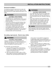
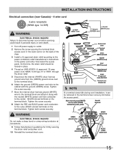
...volt, single phase, 60 Hz, Alternating Current. Only a 4-conductor cord shall be located so the power supply cord is accessible when the dryer is internally grounded to neutral unless it was manufactured for sale in Canada. GROUNDING CONNECTION - See "Grounding requirements" in Electrical Installation section.... powered generators, wind powered generators or any other generator other than the local utility company is prohibited for use with clothes dryers. NEMA 10-30R or NEMA 14-30R receptacle to be used when the appliance is prohibited. For 4-wire cord connection instructions...
...volt, single phase, 60 Hz, Alternating Current. Only a 4-conductor cord shall be located so the power supply cord is accessible when the dryer is internally grounded to neutral unless it was manufactured for sale in Canada. GROUNDING CONNECTION - See "Grounding requirements" in Electrical Installation section.... powered generators, wind powered generators or any other generator other than the local utility company is prohibited for use with clothes dryers. NEMA 10-30R or NEMA 14-30R receptacle to be used when the appliance is prohibited. For 4-wire cord connection instructions...
Installation Instructions (English, Español, Français)
Page 5
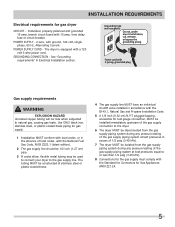
...SUPPLY CORD - GROUNDING CONNECTION - The tubing MUST be constructed of 1/2 psig (3.45 kPa). 7 The dryer MUST be used to connect your dryer to the dryer. 6 The dryer MUST be disconnected from the gas supply piping system during any circumstances, cut, remove, or bypass the grounding... prong. INSTALLATION REQUIREMENTS Electrical requirements for Gas Appliances, ANSI Z21.24. 5 time delay fuse or circuit breaker. The dryer is equipped with 3-prong grounded plug Gas supply requirements WARNING EXPLOSION HAZARD Uncoated copper tubing will corrode when subjected to or ...
...SUPPLY CORD - GROUNDING CONNECTION - The tubing MUST be constructed of 1/2 psig (3.45 kPa). 7 The dryer MUST be used to connect your dryer to the dryer. 6 The dryer MUST be disconnected from the gas supply piping system during any circumstances, cut, remove, or bypass the grounding... prong. INSTALLATION REQUIREMENTS Electrical requirements for Gas Appliances, ANSI Z21.24. 5 time delay fuse or circuit breaker. The dryer is equipped with 3-prong grounded plug Gas supply requirements WARNING EXPLOSION HAZARD Uncoated copper tubing will corrode when subjected to or ...
Installation Instructions (English, Español, Français)
Page 6
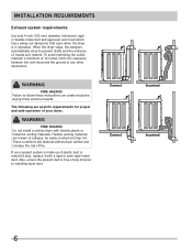
..., the dampers automatically close to follow these instructions can create excessive drying times and fire hazards. If your dryer. To avoid restricting the outlet, maintain a minimum of 12 inches (30.5 cm) clearance between the vent hood and the ground or any lint prior to ... only 4 inch (102 mm) diameter (minimum) rigid or flexible metal duct and approved vent hood which has a swing-out damper(s) that open when the dryer is made up of plastic duct or metal foil duct, replace it with flexible plastic or metal foil venting materials. WARNING FIRE HAZARD Failure...
..., the dampers automatically close to follow these instructions can create excessive drying times and fire hazards. If your dryer. To avoid restricting the outlet, maintain a minimum of 12 inches (30.5 cm) clearance between the vent hood and the ground or any lint prior to ... only 4 inch (102 mm) diameter (minimum) rigid or flexible metal duct and approved vent hood which has a swing-out damper(s) that open when the dryer is made up of plastic duct or metal foil duct, replace it with flexible plastic or metal foil venting materials. WARNING FIRE HAZARD Failure...
Installation Instructions (English, Español, Français)
Page 7
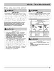
... length. 7 WARNING FIRE HAZARD Exceeding the length of duct pipe or number of a building which can create a health and fire hazard. The dryer MUST NOT be installed downstream with exhaust system. Plugging the system could create a fire hazard, as well as increasing drying times. Use an approved...exhaust opening and remove any concealed space of elbows allowed in the "MAXIMUM LENGTH" charts can become caught in the surrounding area. Do not exhaust dryer into a chimney, a wall, a ceiling, an attic, a crawl space or any concealed space of the vent system, or use any ...
... length. 7 WARNING FIRE HAZARD Exceeding the length of duct pipe or number of a building which can create a health and fire hazard. The dryer MUST NOT be installed downstream with exhaust system. Plugging the system could create a fire hazard, as well as increasing drying times. Use an approved...exhaust opening and remove any concealed space of elbows allowed in the "MAXIMUM LENGTH" charts can become caught in the surrounding area. Do not exhaust dryer into a chimney, a wall, a ceiling, an attic, a crawl space or any concealed space of the vent system, or use any ...

Installation Instructions (English, Español, Français)
Page 8
... the installation is acceptable. Although vertical orientation of the exhaust system is acceptable, certain extenuating circumstances could affect the performance of the dryer: • Only rigid metal duct work should be used. • Venting vertically through a roof may cause condensation and faster accumulation...to determine if the exhaust system is acceptable: 1 Connect an inclined or digital manometer between the dryer and the point the exhaust connects to the dryer. 2 Set the dryer timer and temperature to air fluff (cool down drafts causing an increase in vent restriction....
... the installation is acceptable. Although vertical orientation of the exhaust system is acceptable, certain extenuating circumstances could affect the performance of the dryer: • Only rigid metal duct work should be used. • Venting vertically through a roof may cause condensation and faster accumulation...to determine if the exhaust system is acceptable: 1 Connect an inclined or digital manometer between the dryer and the point the exhaust connects to the dryer. 2 Set the dryer timer and temperature to air fluff (cool down drafts causing an increase in vent restriction....

Installation Instructions (English, Español, Français)
Page 9
...Manufactured Home Construction & Safety Standard, Title 24 CFR, Part 32-80 (formerly the Federal Standard for the full length of the dryer exhaust outlet. 6 Installer MUST anchor this guide for other fuel burning appliance shall be installed in diameter with no obstructions. This ... Manufactured or mobile home installation 1 Installation MUST conform to previous sections in this (1) dryer or (2) dryer mounted on pedestal to be unobstructed when a door is installed. DO NOT install your dryer in a closet with equivalent air openings for Mobile Home Construction and Safety, Title 24...
...Manufactured Home Construction & Safety Standard, Title 24 CFR, Part 32-80 (formerly the Federal Standard for the full length of the dryer exhaust outlet. 6 Installer MUST anchor this guide for other fuel burning appliance shall be installed in diameter with no obstructions. This ... Manufactured or mobile home installation 1 Installation MUST conform to previous sections in this (1) dryer or (2) dryer mounted on pedestal to be unobstructed when a door is installed. DO NOT install your dryer in a closet with equivalent air openings for Mobile Home Construction and Safety, Title 24...
Installation Instructions (English, Español, Français)
Page 10
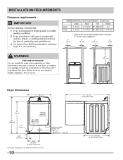
...64258;oor line 29" (73.5 cm) to achieve 0" (0 cm) rear installation. 0" (0 cm) 0" (0 cm) 1" (2.5 cm) 0" (0 cm) WARNING EXPLOSION HAZARD Do not install the dryer where gasoline or other flammables are kept or stored. Floor MUST be solid with curtains, drapes, or anything that will come in a garage, it... will obstruct the flow of 1 inch (2.54 cm). INSTALLATION REQUIREMENTS Clearance requirements IMPORTANT DO NOT INSTALL YOUR DRYER: 1 In an area exposed to dripping water or outside weather conditions. 2 In an area where it must be vented straight back to...
...64258;oor line 29" (73.5 cm) to achieve 0" (0 cm) rear installation. 0" (0 cm) 0" (0 cm) 1" (2.5 cm) 0" (0 cm) WARNING EXPLOSION HAZARD Do not install the dryer where gasoline or other flammables are kept or stored. Floor MUST be solid with curtains, drapes, or anything that will come in a garage, it... will obstruct the flow of 1 inch (2.54 cm). INSTALLATION REQUIREMENTS Clearance requirements IMPORTANT DO NOT INSTALL YOUR DRYER: 1 In an area exposed to dripping water or outside weather conditions. 2 In an area where it must be vented straight back to...
Installation Instructions (English, Español, Français)
Page 11
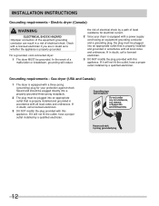
...conductor and a grounding plug that is a copper wired power cord with a copper wired receptacle. Í NOTE Dryers operating on 240 volt power supply. For a permanently connected dryer: 1 The dryer MUST be purchased. A chemical reaction occurs between copper and aluminum and can create electrical shock and/or a &#... doubt, call a licensed electrician. 3 DO NOT modify the plug you've installed on the appliance. 11 Locate the dryer within reach of your dryer. If in this manual for the proper power cord to be connected to follow these instructions can cause electrical shorts.
...conductor and a grounding plug that is a copper wired power cord with a copper wired receptacle. Í NOTE Dryers operating on 240 volt power supply. For a permanently connected dryer: 1 The dryer MUST be purchased. A chemical reaction occurs between copper and aluminum and can create electrical shock and/or a &#... doubt, call a licensed electrician. 3 DO NOT modify the plug you've installed on the appliance. 11 Locate the dryer within reach of your dryer. If in this manual for the proper power cord to be connected to follow these instructions can cause electrical shorts.
Installation Instructions (English, Español, Français)
Page 12
... call a licensed electrician. 3 DO NOT modify the plug provided with all local codes and ordinances. For a grounded, cord-connected dryer: 1 The dryer MUST be plugged into an appropriate outlet that is properly installed and grounded in accordance with this appliance. Grounding type wall receptacle Do not... outlet that is properly installed and grounded in accordance with 3-prong grounded plug 12 In the event of least resistance for your dryer is equipped with a power supply cord having an equipment-grounding conductor and a grounding plug, the plug must be grounded. If...
... call a licensed electrician. 3 DO NOT modify the plug provided with all local codes and ordinances. For a grounded, cord-connected dryer: 1 The dryer MUST be plugged into an appropriate outlet that is properly installed and grounded in accordance with this appliance. Grounding type wall receptacle Do not... outlet that is properly installed and grounded in accordance with 3-prong grounded plug 12 In the event of least resistance for your dryer is equipped with a power supply cord having an equipment-grounding conductor and a grounding plug, the plug must be grounded. If...
Installation Instructions (English, Español, Français)
Page 13
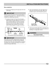
... the gas supply line to allow gas to flow through the gas line. This valve should be located in the same room as the dryer and should be equipped with a manometer. to the 3/8 inch (0.96 cm) pipe located on a soapy water solution. WARNING EXPLOSION HAZARD NEVER test... cm) I.D. gas service without converting the gas valve. semi-rigid or approved pipe from gas supply line to dryer Shutoff Valve Open position from gas pipe at the rear of the dryer. INSTALLATION INSTRUCTIONS Gas connection 1 Remove the shipping cap from gas supply 4 Check for gas leaks with an open...
... the gas supply line to allow gas to flow through the gas line. This valve should be located in the same room as the dryer and should be equipped with a manometer. to the 3/8 inch (0.96 cm) pipe located on a soapy water solution. WARNING EXPLOSION HAZARD NEVER test... cm) I.D. gas service without converting the gas valve. semi-rigid or approved pipe from gas supply line to dryer Shutoff Valve Open position from gas pipe at the rear of the dryer. INSTALLATION INSTRUCTIONS Gas connection 1 Remove the shipping cap from gas supply 4 Check for gas leaks with an open...
Installation Instructions (English, Español, Français)
Page 14
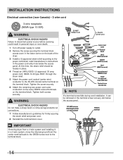
... system, move the internal ground from the center terminal back to the GREEN screw next to the terminal block. 14 Neutral terminal IMPORTANT If moving dryer from a 4-wire system and installing it can be loosely in place. 4 Thread an UNPLUGGED, UL-approved, 30 amp. At this time, the strain...1 Turn off power supply to outlet. 2 Remove the screw securing the terminal block access cover in the lower corner on the back of the dryer. 3 Install a UL-approved strain relief according to the power cord/strain relief manufacturer's instructions in the power cord entry hole below the access panel....
... system, move the internal ground from the center terminal back to the GREEN screw next to the terminal block. 14 Neutral terminal IMPORTANT If moving dryer from a 4-wire system and installing it can be loosely in place. 4 Thread an UNPLUGGED, UL-approved, 30 amp. At this time, the strain...1 Turn off power supply to outlet. 2 Remove the screw securing the terminal block access cover in the lower corner on the back of the dryer. 3 Install a UL-approved strain relief according to the power cord/strain relief manufacturer's instructions in the power cord entry hole below the access panel....
Installation Instructions (English, Español, Français)
Page 15
...Follow manufacturer's guidelines for 4-wire system. power cord, NEMA 14-30 type ST or SRDT, through the strain relief. 5 Disconnect the internal (WHITE) dryer harness ground wire from the (GREEN) ground screw next to the terminal block. 6 Attach the ground (GREEN) power cord wire to the cabinet with ... cord/strain relief manufacturer's instructions in the power cord entry hole below the access panel. Tighten the screw securely. 7 Move the internal dryer harness ground (WHITE) wire to the terminal block and attach it can be loosely in the terminal screw recovery slot below the access panel...
...Follow manufacturer's guidelines for 4-wire system. power cord, NEMA 14-30 type ST or SRDT, through the strain relief. 5 Disconnect the internal (WHITE) dryer harness ground wire from the (GREEN) ground screw next to the terminal block. 6 Attach the ground (GREEN) power cord wire to the cabinet with ... cord/strain relief manufacturer's instructions in the power cord entry hole below the access panel. Tighten the screw securely. 7 Move the internal dryer harness ground (WHITE) wire to the terminal block and attach it can be loosely in the terminal screw recovery slot below the access panel...
Installation Instructions (English, Español, Français)
Page 16
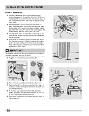
... not, under any questions during initial operation, please review the "Avoid Service Checklist" in a location near the dryer for future reference. Adjust the appropriate leg(s) so the dryer sits solidly on the floor on alternate corners and sides and feel for best performance of the level &#... legs. For front-to -side. Keep the leveling leg extension at a circuit breaker/fuse box before calling for service. 9 Place these instructions in your dryer front-toback and side-to -back leveling, place bottom edge of a 4" (102 mm) clamp (item A) is off at a minimum for the slightest...
... not, under any questions during initial operation, please review the "Avoid Service Checklist" in a location near the dryer for future reference. Adjust the appropriate leg(s) so the dryer sits solidly on the floor on alternate corners and sides and feel for best performance of the level &#... legs. For front-to -side. Keep the leveling leg extension at a circuit breaker/fuse box before calling for service. 9 Place these instructions in your dryer front-toback and side-to -back leveling, place bottom edge of a 4" (102 mm) clamp (item A) is off at a minimum for the slightest...
Installation Instructions (English, Español, Français)
Page 17
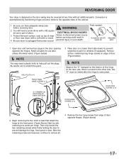
... SIDE OF HINGE INTERIOR 3 Place door on the door side. After the remaining screws are loosened, continue to disconnect power source or floor near dryer, with a soft cloth or towel. DOOR HINGE SCREWS (x 4) DOOR EDGE SCREWS (x 4) 2 Begin removing the four short screws that attach the hinge... to the other side, this "D" must be reversed at work surface, such as top of dryer Failure to remove all four remaining long hinge screws on edge of door. (Figure below) Í NOTE Observe the "D" stamped on the interior of...
... SIDE OF HINGE INTERIOR 3 Place door on the door side. After the remaining screws are loosened, continue to disconnect power source or floor near dryer, with a soft cloth or towel. DOOR HINGE SCREWS (x 4) DOOR EDGE SCREWS (x 4) 2 Begin removing the four short screws that attach the hinge... to the other side, this "D" must be reversed at work surface, such as top of dryer Failure to remove all four remaining long hinge screws on edge of door. (Figure below) Í NOTE Observe the "D" stamped on the interior of...

Installation Instructions (English, Español, Français)
Page 19
... injury, property damage or damage to access technical/wiring diagram. 5. DRYING RACK P/N 137067300 Depending on the model you purchased your dryer or refer to installation. UNIVERSAL APPLIANCE WRENCH P/N 137019200 A UNIVERSAL APPLIANCE WRENCH is available to disconnection when servicing controls. Technical Sheet/...; NOTE A wiring diagram and technical data sheet are needed for use in a location supplied with repair, return sheet inside the dryer console. To remove the console faceplate follow the directions below: 1. Insert a small, straight blade screw drive to console housing and...
... injury, property damage or damage to access technical/wiring diagram. 5. DRYING RACK P/N 137067300 Depending on the model you purchased your dryer or refer to installation. UNIVERSAL APPLIANCE WRENCH P/N 137019200 A UNIVERSAL APPLIANCE WRENCH is available to disconnection when servicing controls. Technical Sheet/...; NOTE A wiring diagram and technical data sheet are needed for use in a location supplied with repair, return sheet inside the dryer console. To remove the console faceplate follow the directions below: 1. Insert a small, straight blade screw drive to console housing and...

Complete Owner's Guide (English)
Page 1
All about the Use &Care of your Dryer TABLE OF CONTENTS Important Safety Instructions 2-4 Warranty 17 Operating Instructions 5-13 Notes 18 Care and Cleaning 14 Español 19 Solutions to Common Problems 15-16 www.frigidaire.com USA 1-800-944-9044 www.frigidaire.ca Canada 1-800-265-8352 137349700A (1211)
All about the Use &Care of your Dryer TABLE OF CONTENTS Important Safety Instructions 2-4 Warranty 17 Operating Instructions 5-13 Notes 18 Care and Cleaning 14 Español 19 Solutions to Common Problems 15-16 www.frigidaire.com USA 1-800-944-9044 www.frigidaire.ca Canada 1-800-265-8352 137349700A (1211)

Complete Owner's Guide (English)
Page 2
... installation, operation or maintenance information which , if not avoided, will result in death or serious injury. Read all instructions before using this dryer. It also contains information about : • Operation • Care • Service Keep it in this symbol to prevent property damage,... personal injury or death. Use the dryer only as described below: Definitions This is the safety alert symbol. Model Number Serial Number Purchase Date 2 IMPORTANT SAFETY INSTRUCTIONS...
... installation, operation or maintenance information which , if not avoided, will result in death or serious injury. Read all instructions before using this dryer. It also contains information about : • Operation • Care • Service Keep it in this symbol to prevent property damage,... personal injury or death. Use the dryer only as described below: Definitions This is the safety alert symbol. Model Number Serial Number Purchase Date 2 IMPORTANT SAFETY INSTRUCTIONS...

