English manual
Page 11
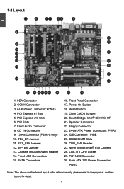
AUX Power Connector: PWR3 4. CD_IN Connector 9. 1394a Connector (P35A-S only) 10. Power On Button 18. 1-2 Layout 7 6 54 32 1 1 8 30 29 9 10 28 11 12 13 27 14 26 25 15 24 16 17 18 ... 20 21 29 22 23 1. COM1 Connector 3. TBL_EN Jumper 11. WP_EN Jumper 13. South Bridge: Intel® ICH9/ICH9R 21. DDR2 DIMM Slots 26. LGA 775 CPU Socket 29. FAN1/2/3 Connector 30. 8-pin ATX 12V Power Connector: PWR2 Note : The above motherboard layout is for reference only, please refer to the...
AUX Power Connector: PWR3 4. CD_IN Connector 9. 1394a Connector (P35A-S only) 10. Power On Button 18. 1-2 Layout 7 6 54 32 1 1 8 30 29 9 10 28 11 12 13 27 14 26 25 15 24 16 17 18 ... 20 21 29 22 23 1. COM1 Connector 3. TBL_EN Jumper 11. WP_EN Jumper 13. South Bridge: Intel® ICH9/ICH9R 21. DDR2 DIMM Slots 26. LGA 775 CPU Socket 29. FAN1/2/3 Connector 30. 8-pin ATX 12V Power Connector: PWR2 Note : The above motherboard layout is for reference only, please refer to the...